Fiber Bragg Grating Temperature Sensor and Its Probe

A technology of temperature sensor and fiber grating

Inactive Publication Date: 2011-12-14
LASER RES INST OF SHANDONG ACAD OF SCI +1
View PDF5 Cites 23 Cited by
  • Summary
  • Abstract
  • Description
  • Claims
  • Application Information

AI Technical Summary

Problems solved by technology

Not suitable for clinical application of microwave hyperthermia for bone tumors

Method used


Image

  • Fiber Bragg Grating Temperature Sensor and Its Probe
  • Fiber Bragg Grating Temperature Sensor and Its Probe
  • Fiber Bragg Grating Temperature Sensor and Its Probe

Examples


Embodiment 1

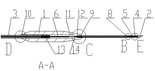
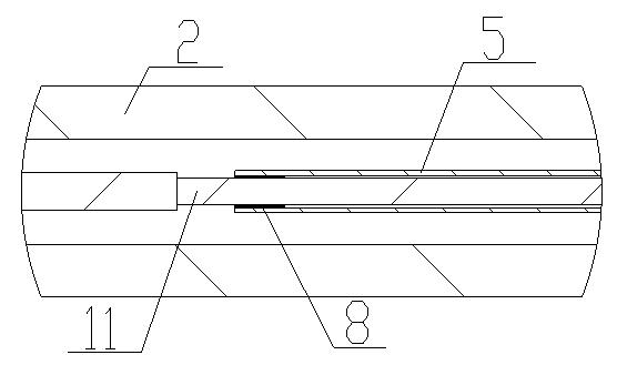
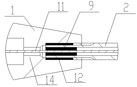
[0018] A fiber grating temperature sensor probe, which includes a needle 2 and a handle 1 connected together, the needle 2 is a round rod with a needle point, a blind hole is arranged in the center of the bottom surface of one end of the round rod, and the blind hole extends to nearly The other end of the round rod has a needle point; a fiber Bragg grating 4 is fixed through a quartz glass capillary 5 in the blind hole. Setting the fiber Bragg grating 4 in the blind hole refers to stripping the coating layer of the fiber Bragg grating 4 and its root 5mm tail fiber 11 and placing it in the fiber Bragg grating 4 root 5mm tail fiber at the rear part of the quartz glass capillary 5. After the surface of 11 is coated with glue, insert it into the quartz glass capillary 5 close to the front end, then insert the fiber Bragg grating 4 together with the quartz glass capillary 5 into the blind hole of the needle 2 and apply glue to the root of the needle 2, connect the needle 2 and the t...

Embodiment 2

[0022] The similarities between this embodiment and Embodiment 1 will not be repeated, the difference is that it is a fiber grating temperature sensor, which includes a probe and a demodulation system connected thereto. System block diagram as Figure 5 As shown, the narrowband light output by the laser enters the sensing fiber grating through the isolator and coupler, and the optical path of the narrowband laser is tuned through the signal generator, and the central wavelength of the output light is periodically changed to scan the reflection of the sensing fiber grating Spectrum. When the output spectrum of the laser changes, the change of the received light intensity of the detector reflects the matching condition of the output spectrum of the laser and the reflection spectrum of the sensing fiber grating. Theoretically, when the central wavelength of the laser and the sensing FBG is completely matched, the optical power received by the detector reaches the maximum value. ...


PUM

PropertyMeasurementUnit
diameteraaaaaaaaaa
depthaaaaaaaaaa
lengthaaaaaaaaaa

Abstract

The invention relates to a fiber grating temperature sensor which comprises a probe and a demodulating system connected with the probe, wherein the probe comprises a needle head and a handle which are connected together. The fiber grating temperature sensor is characterized in that the needle head is an austenitic stainless steel round bar with a needle point, the center of the bottom surface at one end of the austenitic stainless steel round bar is provided with a blind hole, and the blind hole extends close to the other end of the austenitic stainless steel round bar; and a fiber bragg grating is arranged in the blind hole. The invention is mainly used for manufacturing fiber grating temperature sensors for microwave thermotherapy of bone tumors.

Description

technical field [0001] The invention relates to an optical fiber grating temperature sensor and a probe thereof, in particular to an optical fiber Bragg grating temperature sensor, which is especially suitable for clinical application of microwave hyperthermia for bone tumors. Background technique [0002] Tumor is a kind of disease that seriously threatens human life and health. One of its characteristics is that it is very diffuse, and because there is no clear boundary between tumor cells and surrounding normal human tissue cells, it is difficult to completely remove tumor cells with general surgical treatment methods, and it is easy to relapse after surgery. Although radiotherapy and chemotherapy can kill tumor cells, they also damage a large number of normal tissue cells, which further deteriorates the patient's physical condition and makes it difficult to receive follow-up treatment. At present, countries around the world have successively developed the use of microwa...

Claims


Application Information

Patent Timeline
Patent Type & Authority Applications(China)
IPC IPC(8): A61B5/01A61N5/02G01K11/32G01K11/3206
Inventor 赵维崧
Owner LASER RES INST OF SHANDONG ACAD OF SCI
Why Eureka
Try Eureka