Method and apparatus for active temperature control of susceptors

a susceptor and active temperature technology, applied in the field of thermoplastic processing of substrates, can solve the problems of excessive diffusion, time and energy required, and inability to provide optimal, and achieve the effects of low thermal conductance, high thermal conductance, and adversely affecting device performan

Inactive Publication Date: 2005-08-18
TOKYO ELECTRON LTD
View PDF25 Cites 23 Cited by
  • Summary
  • Abstract
  • Description
  • Claims
  • Application Information

AI Technical Summary

Benefits of technology

[0012] The periphery of a wafer changes temperature at a different rate than does the bulk of the wafer. This difference can lead to an edge effect that can adversely affect device performance. Accordingly, the inventors have determined that what is needed is a way to spatially vary the thermal conductance of a structure used to heat or cool wafers.
[0013] The inventors have further determined that it is important to temporally vary the thermal conductance of a structure used to heat or cool wafers. The inventors have determined that it is desirable to have a very high thermal conductance when the wafer is at a temperature significantly different from the desired temperature so that one can transfer a lot of heat into or out of a wafer so that the wafer reaches a desired temperature as quickly as possible. However, when the wafer is at or close to a desired temperature, it is advantageous to have a low thermal conductance.
[0014] The presence of a temperature sensor (e.g., thermocouple) can provide accurate measurements of the temperature at the sensory location. In some instances, such sensors are used to determine whether a valve should be opened or closed, thereby controlling the amount of coolant allowed to flow and the amount of energy being dissipated. However, thermocouples only provide temperature measurements at the location of the thermocouple. In addition, thermocouples break due to thermal cycling, and require electrical connections, including electrical insulation, between the thermocouple and their associated instrumentation. Furthermore, in a system that provides for enhanced rates of heating and cooling, the adverse effects of thermal cycling are exacerbated. Accordingly, the inventors have determined that what is needed is a way to sense the temperature so that the controller can adjust the valve and heater appropriately.
[0015] In an effort to address the important issues identified by the inventors and discussed above, the inventors have constructed an apparatus and method as described in detail below. Accordingly, the present invention advantageously provides an apparatus and method for reducing thermal burden on a wafer during processing.

Problems solved by technology

Simply heating and cooling the wafer by controlling the temperature of a heat transfer solution and then circulating that solution through channels formed in a wafer support structure will not provide optimal results.
This method suffers from the amount of time and energy required to change the heat transfer solution from one temperature to another.
Unfortunately, the cumulative thermal burden of a process can cause excessive diffusion.
Two contributing factors to the thermal burden of a process are the time required to heat a wafer and the time required to cool the wafer.
However, existing systems, such as flash lamp-based heaters, inject more heat into the middle of the wafer than into the radial portions of the wafer, which results in non-uniform heating.
Compounding this problem is the insulating effect of air around the periphery of the wafer that impedes heat flow into and out of the wafer.
However, such systems are limited by the capacity of the structure to transfer heat into and out of the fluid.
Although such systems are capable of transferring huge quantities of heat, those systems do so with the assistance of large volumes of heat exchanging equipment.

Method used


Image

  • Method and apparatus for active temperature control of susceptors
  • Method and apparatus for active temperature control of susceptors
  • Method and apparatus for active temperature control of susceptors

Examples


Embodiment Construction

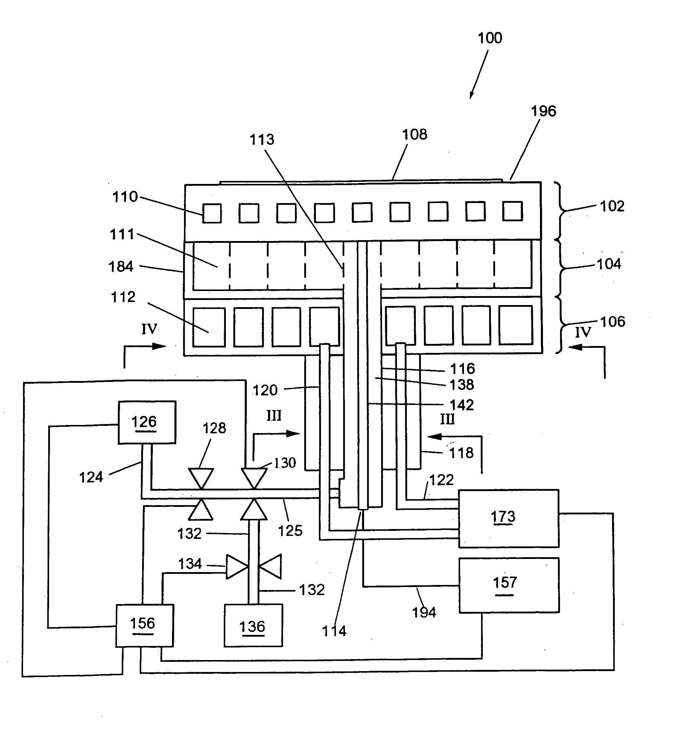
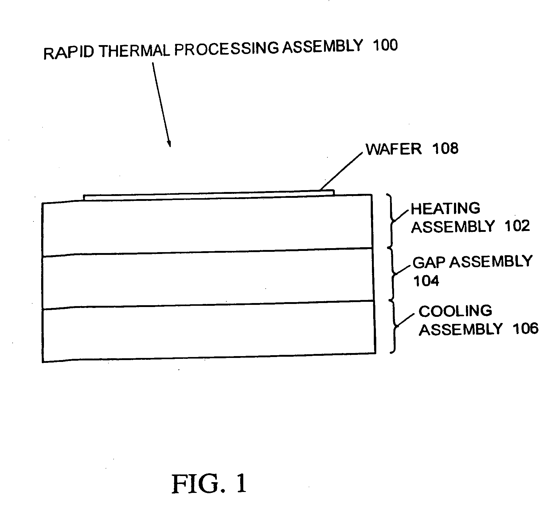
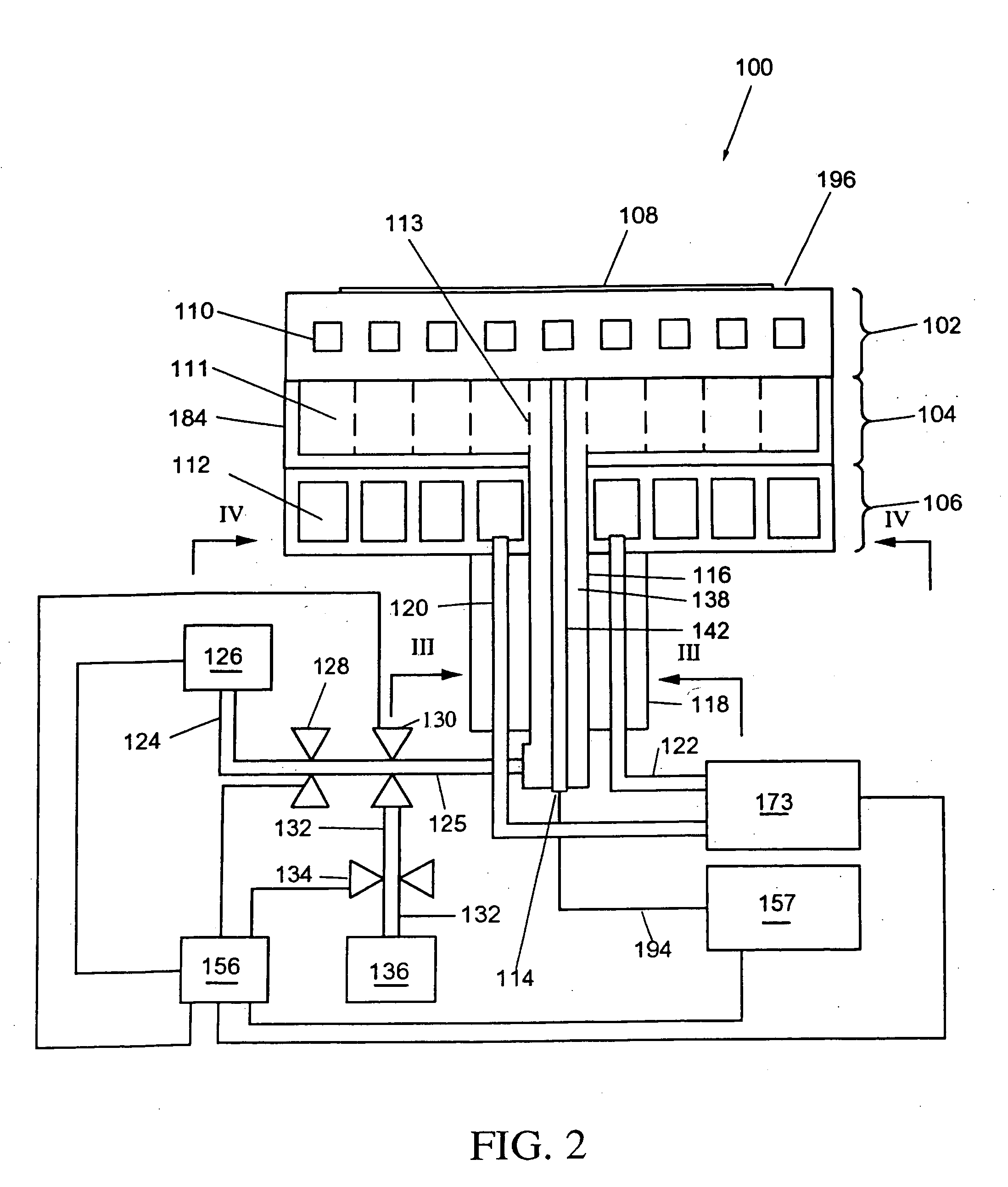
[0036] The present invention will now be described with reference to preferred embodiments illustrated in the figures. The present invention generally relates to a method and an apparatus for actively controlling the temperature of a susceptor. The apparatus supports a wafer with a heating assembly, beneath which is a thermal conductance region whose thermal conductance is regulated. Furthermore, a cooling assembly is provided beneath the thermal conductance region. The present invention further includes several methods of operating the apparatus.

[0037] Referring now to the drawings, FIG. 1 is an overview of a preferred embodiment of a rapid thermal processing assembly or apparatus 100, which acts essentially as, for example, a novel thermal switch for heating and cooling susceptors used for processing semiconductor wafers. The apparatus 100 generally includes a heating assembly 102, a cooling assembly 106, and a gap assembly or device 104 provided within a thermal conductance regi...


PUM

PropertyMeasurementUnit
thickaaaaaaaaaa
poweraaaaaaaaaa
heightaaaaaaaaaa

Abstract

A method and an apparatus utilized for thermal processing of substrates during semiconductor manufacturing. The method includes heating the substrate to a predetermined temperature using a heating assembly, cooling the substrate to the predetermined temperature using a cooling assembly located such that a thermal conductance region is provided between the heating and cooling assemblies, and adjusting a thermal conductance of the thermal conductance region to aid in heating and cooling of the substrate. The apparatus includes a heating assembly, a cooling assembly located such that a thermal conductance region is provided between the heating and cooling assemblies, and a structure or configuration for adjusting a thermal conductance of the thermal conductance region.

Description

CROSS-REFERENCE TO RELATED APPLICATIONS [0001] This application is related to co-pending application Ser. No. 60 / 156,595, filed Sep. 29, 1999 and International Application No. PCT / US00 / 25503, filed Sep. 18, 2000. This application is related to and claims priority to International Application No. PCT / US02 / 03403, filed on Feb. 25, 2002. The contents of those applications are incorporated herein by reference.BACKGROUND OF THE INVENTION [0002] 1. Field of the Invention [0003] The present invention relates generally to thermal processing of substrates during semiconductor manufacturing. [0004] 2. Discussion of the Background [0005] The increasing sophistication of semiconductor technology, and the never ending reduction in minimum line widths, is causing process engineers to demand increasing capabilities from the equipment used to manufacture semiconductor integrated circuits. These requirements are leading in particular to a need to minimize the cumulative thermal burden of integrated ...

Claims


Application Information

Patent Timeline
Patent Type & Authority Applications(United States)
IPC IPC(8): H01L21/00H01L21/26H01L21/687
CPCH01L21/67109H01L21/68785H01L21/68757H01L21/67248
Inventor STRANG, ERIC J.JOHNSON, WAYNE L.
Owner TOKYO ELECTRON LTD
Why Eureka
Try Eureka