Microwave temperature measurement system based on fluorescence fiber temperature measurement

A technology of fluorescent optical fiber and optical fiber, applied in thermometers, measuring devices, measuring heat, etc., can solve the problems of inaccurate temperature measurement, unstable optical power, unstable temperature measurement, etc., and achieve the effect of accurate temperature measurement

Active Publication Date: 2012-04-04
北京东方锐择科技有限公司
View PDF6 Cites 22 Cited by
  • Summary
  • Abstract
  • Description
  • Claims
  • Application Information

AI Technical Summary

Problems solved by technology

Since the object to be measured in microwave equipment generally needs to be continuously rotated to obtain uniform heating, and the optical fiber penetrates into the microwave cavity, it needs a free rotation adapter design, but the semiconductor type and other temperature measurement based on optical power, because the optical fiber needs to The rotation of the measured object and the change of the bending movement of the optical fiber may cause the instability of the optical power, which will affect the instability of the temperature measurement and cause the measured temperature to be inaccurate

Method used


Image

  • Microwave temperature measurement system based on fluorescence fiber temperature measurement
  • Microwave temperature measurement system based on fluorescence fiber temperature measurement
  • Microwave temperature measurement system based on fluorescence fiber temperature measurement

Examples


Embodiment Construction

[0024] The specific implementation manners of the present invention will be further described in detail below in conjunction with the accompanying drawings and embodiments. The following examples are used to illustrate the present invention, but are not intended to limit the scope of the present invention.

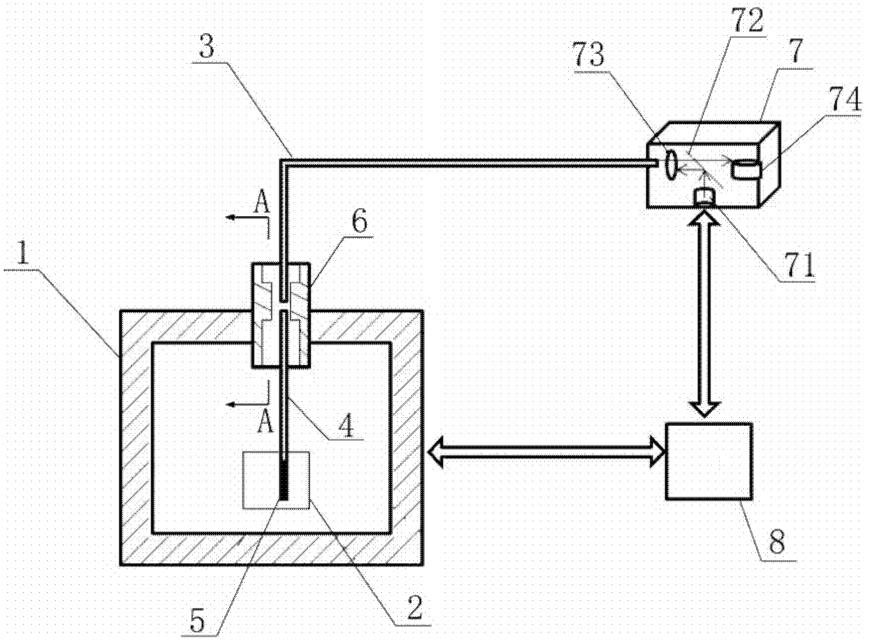
[0025] like figure 1 As shown, it is a schematic structural diagram of a microwave temperature measurement system according to an embodiment of the present invention. The microwave temperature measurement system includes: a measurement device 7 , an external optical fiber 3 , an internal optical fiber 4 , a fluorescent probe 5 , and an optical fiber adapter device 6 . The outer optical fiber 3 is located outside the microwave cavity 1 , and the inner optical fiber 4 is located inside the microwave cavity 1 . The optical fiber transition device 6 is fixed in the aperture of the microwave cavity 1 . One end of the external optical fiber 3 is connected to the measuring devi...


PUM


Abstract

The invention discloses a microwave temperature measurement system based on fluorescence fiber temperature measurement and relates to the field of the microwave and optical fiber sensing technique. The microwave temperature measurement system comprises a measurement device, an external optical fiber, an internal optical fiber, a fluorescent probe and an optical fiber adapter, wherein one end of the external optical fiber is connected with the measurement device; the other end of the external optical fiber is connected with the optical fiber adapter; one end of the internal optical fiber is rotatably connected with the optical fiber adapter; the fluorescent probe is fixed at the other end of the internal optical fiber; the optical fiber adapter is fixed in a bore of a microwave cavity; thefluorescent probe is used for receiving optical signals emitted by the measurement device and transmitting fluorescent signals of fluorescent substances on the fluorescent probe excited by the optical signals; and the measurement device is used for measuring the temperature of substances to be measured according to the fluorescent signals. The system achieves the accurate temperature measurement for the substances to be heated in the microwave cavity in the environments of ultrahigh frequency, strong electromagnetic fields and high interference; the adapter is free from the microwave interference; and the system has little microwave leakage, high stability and is simple in structure and simple and convenient in use.

Description

technical field [0001] The invention relates to the technical field of microwave and optical fiber sensing, in particular to a microwave temperature measurement system based on fluorescent optical fiber temperature measurement. Background technique [0002] Microwave refers to electromagnetic radiation with a frequency range of 300MHZ to 300GHZ in the electromagnetic spectrum, which has the characteristics of high frequency, short wavelength, and ability to penetrate the ionosphere. It can be used in radar, communication, scientific research, microwave energy utilization, etc. After the 1960s, microwave has developed rapidly as a new type of heat source. Its heating characteristics: heat generation on the spot, same heat inside and outside, and instant high temperature without heat transfer process, so it has fast heating speed, high heat utilization rate, and can realize Due to the advantages of fast automatic control, it is widely used in industries such as medical treatm...

Claims


Application Information

Patent Timeline
Patent Type & Authority Applications(China)
IPC IPC(8): G01K11/32
Inventor 连子龙张颖
Owner 北京东方锐择科技有限公司
Why Eureka
Try Eureka