
Groundwater flow speed and flow direction detection method and device using temperature as tracer

A groundwater and tracer technology, applied in measuring devices, speed/acceleration/shock measurement, indication/recording actions, etc., can solve the problems of measurement distortion, result error, high test cost, etc., to ensure accuracy and avoid human errors , the effect of labor saving

Inactive Publication Date: 2010-07-21
HOHAI UNIV
View PDF3 Cites 23 Cited by
  • Summary
  • Abstract
  • Description
  • Claims
  • Application Information

AI Technical Summary

Problems solved by technology

The porous tracer test generally includes a source hole and several monitoring holes. The tracer is injected into the source hole, and the change of the tracer concentration is monitored in the monitoring hole. Due to the large number of holes, the test cost is high. The test period is long; for the single-hole tracer test, it is a flow velocity and flow direction detection method based on the single-hole dilution theory, which is widely used in the current detection of groundwater flow velocity and direction, but in the detection process, the probe needs to be located in the center of the borehole to Accurately measure the flow velocity and flow direction, and because there is a certain gap between the probe size and the borehole size, eccentricity will generally occur during the measurement process, resulting in measurement distortion; and, in order to ensure the accuracy of the measurement results, single-hole tracer The method generally uses radioactive isotopes as tracers, and the use of radioactive isotopes will cause harm to the environment and the health of test personnel.
In the existing detection device, the probe of the device is generally large to place the required modules. Due to the function of the probe, the groundwater will be disturbed by the existence of the probe, thus causing errors in the detected results.

Method used


Image

  • Groundwater flow speed and flow direction detection method and device using temperature as tracer
  • Groundwater flow speed and flow direction detection method and device using temperature as tracer
  • Groundwater flow speed and flow direction detection method and device using temperature as tracer

Examples


Embodiment Construction

[0019] The technical solutions of the present invention will be described in detail below in conjunction with the accompanying drawings.

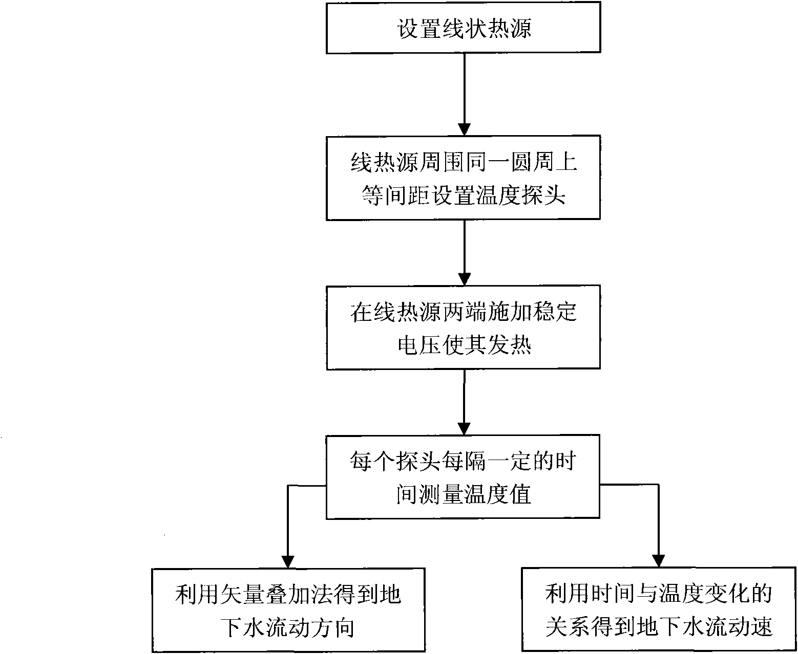
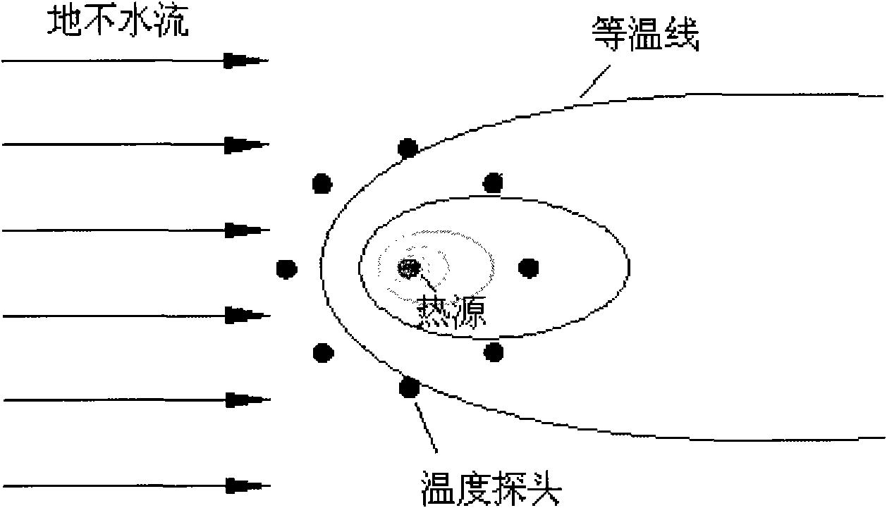
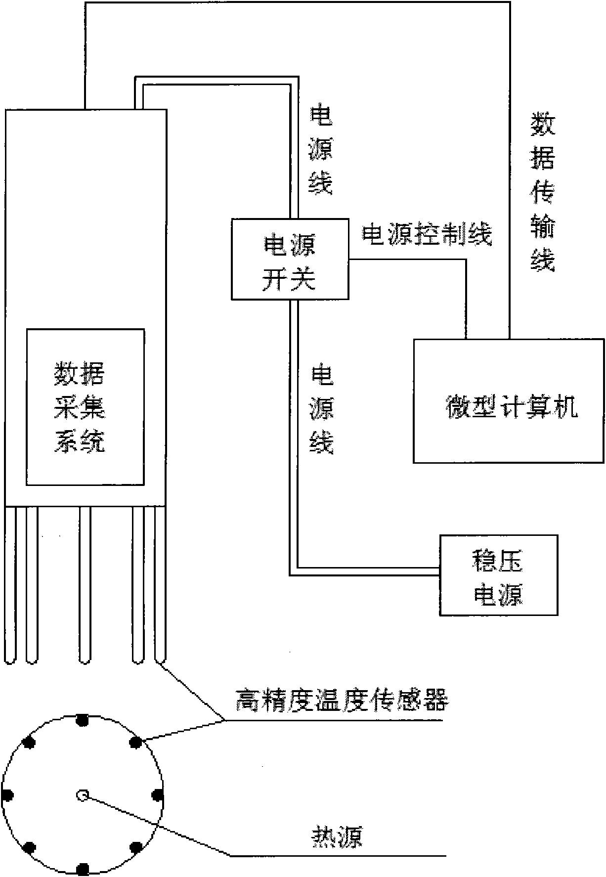
[0020] Such as figure 1 As shown, the method for detecting groundwater flow velocity and direction using temperature as a tracer of the present invention comprises the following steps: (1), getting a linear heat source, and the two ends are connected with a stabilized DC power supply; (2), using the heat source As the center of the circle, several temperature probes are set at equal intervals on the same circle as above; (3), turn on the power switch of the heat source to make the heat source start to generate heat; (4), start counting the time after the heat source starts to generate heat, and record every The temperature value detected by a temperature probe; (5), use the temperature field distribution characteristics under the influence of groundwater flow to judge the flow direction of groundwater; (6), use the relationship between the ...


PUM


Abstract

The invention relates to a method for detecting the flow speed and the flow direction of groundwater by using the temperature as a tracer and a measuring device. The invention adopts a linear heat source, voltage is exerted on the linear heat source so that the linear heat source can generate the heat, a plurality of temperature probes are arranged on the same circumference around the heat source at equal intervals, the values and the time of the temperature received by each probe are different under the effect of the water flow, the temperature received by the probes at the downstream of the heat source is higher than that received by the probes at the upstream of the heat source, the values of the received temperature are used for judging the flow direction of the groundwater, the value of the flow speed of the groundwater is relevant with the time of temperature change received by the probes, and the value of the flow speed of the groundwater is calculated through the time duration from the electrification initiation to the measured temperature change.

Description

technical field [0001] The invention relates to a method and a detection device for detecting the flow direction and velocity of underground water in a rock and soil body, and belongs to the technical field of hydrogeological parameter detection methods and detection devices. Background technique [0002] In the current technology, the commonly used detection method of groundwater flow velocity and direction is the tracer test in the borehole, including multi-hole tracer test and single-hole tracer test. The porous tracer test generally includes a source hole and several monitoring holes. The tracer is injected into the source hole, and the change of the tracer concentration is monitored in the monitoring hole. Due to the large number of holes, the test cost is high. The test period is long; for the single-hole tracer test, it is a flow velocity and flow direction detection method based on the single-hole dilution theory, which is widely used in the current detection of grou...

Claims


Application Information

Patent Timeline
IPC IPC(8): G01P5/10G01P13/00
Inventor 梁越陈建生陈亮王宇铭
Owner HOHAI UNIV
Learn More