
Method and device for monitoring carrier frequency stability of transmitters in a common wave network

a transmitter and carrier frequency technology, applied in broadcast transmission systems, digital transmission, electrical equipment, etc., can solve the problems of undesirable reception, non-uniform monitoring of the carrier frequency of all the transmitters participating in the single-frequency network, and synchronicity evaluation

Active Publication Date: 2010-02-23
ROHDE & SCHWARZ GMBH & CO KG
View PDF14 Cites 4 Cited by
  • Summary
  • Abstract
  • Description
  • Claims
  • Application Information

AI Technical Summary

Problems solved by technology

The disadvantage with this method is the fact that the synchronicity of the carrier frequency is evaluated by each transmitter individually.
Accordingly, this transmitter-specific evaluation of the frequency synchronicity of the carrier frequency may be associated with a certain transmitter-specific measurement and evaluation error, which can lead to a non-uniform monitoring of the carrier frequencies of all the transmitters participating in the single-frequency network.
All of these disadvantages can lead to an undesirable reception of different carrier frequencies of the individual transmitters in a receiver positioned anywhere within the transmission range of the single-frequency network.

Method used


Image

  • Method and device for monitoring carrier frequency stability of transmitters in a common wave network
  • Method and device for monitoring carrier frequency stability of transmitters in a common wave network
  • Method and device for monitoring carrier frequency stability of transmitters in a common wave network

Examples


first embodiment

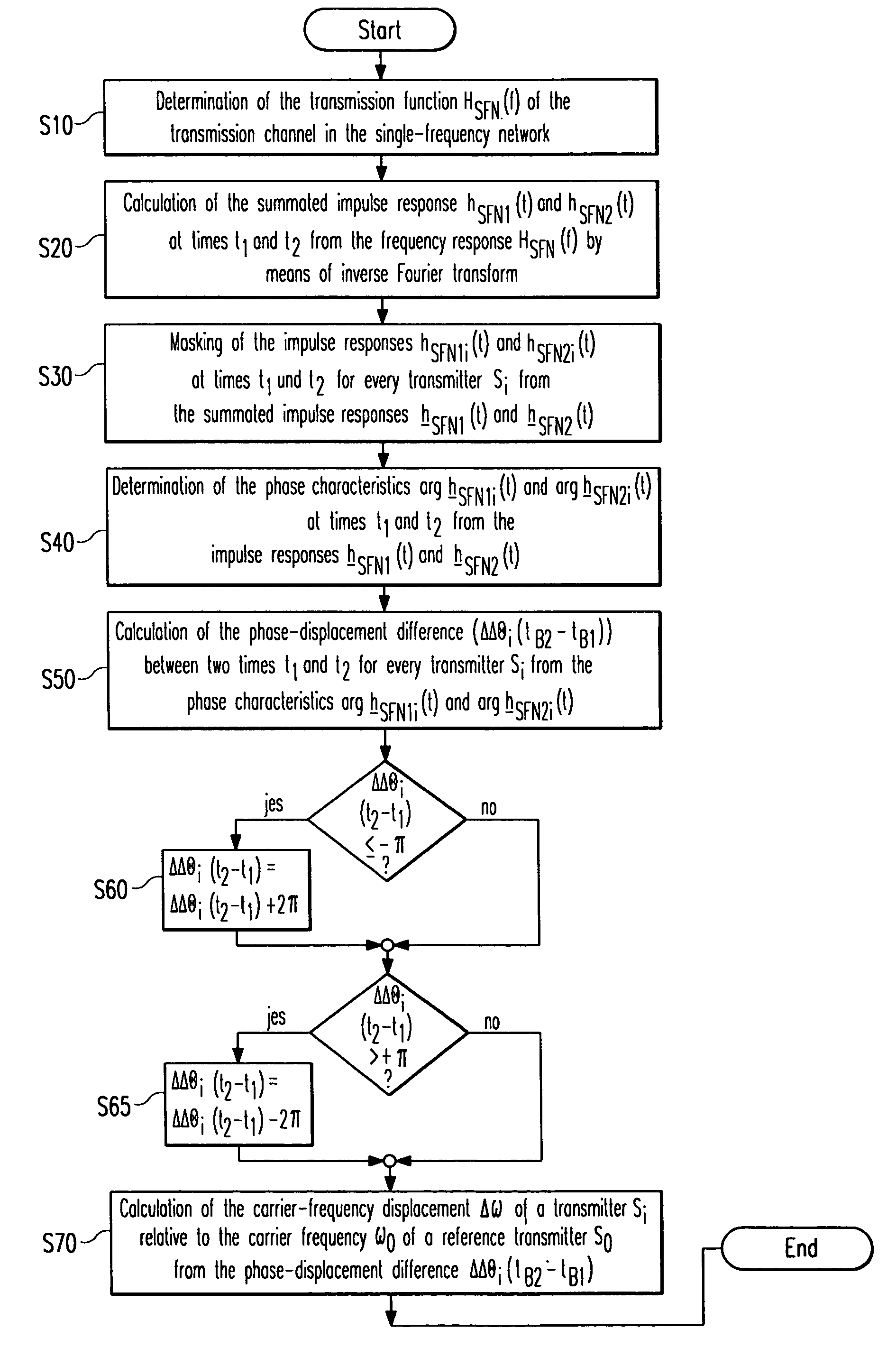
[0051]The first embodiment for monitoring the carrier-frequency stability of transmitters in a single-frequency network is therefore derived from the procedural stages presented below, as shown in FIG. 4A:

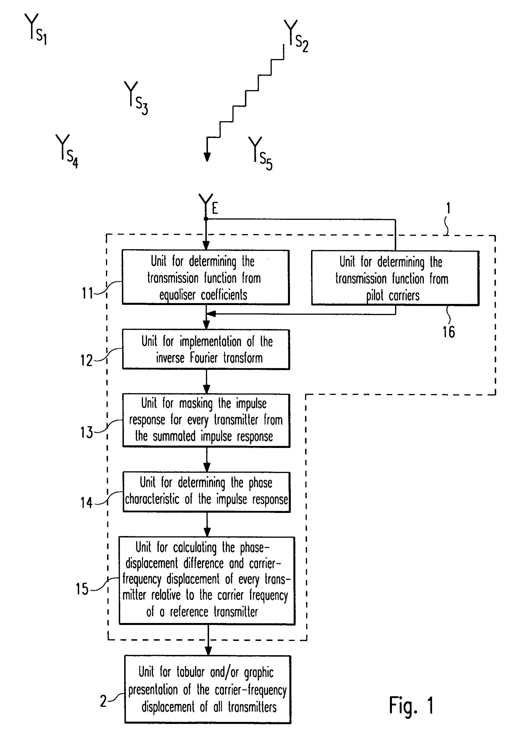
[0052]In procedural stage S10, the transmission function HSFN(f) of the transmission channel of the individual transmitters S0, . . . , S1, . . . , Sn of the single-frequency network to the receiver device E is determined. For this purpose, the characteristic of the transmission function HSFN(f) can be determined from the coefficients of the equaliser integrated in the receiver device E, which, in the case of an equaliser adapted to the transmission channel, correspond to the coefficients of the transmission function HSFN(f).

[0053]In procedural stage S20, the characteristics of the associated complex, summated impulse responses hSFN1(t) and hSFN2(t) at the two times tB1 of the time slot ΔtB1 and tB2 of the time slot ΔtB2 are calculated by means of discrete, inverse Fourier transfor...

second embodiment

[0064]Since, over the time t, additional phase changes resulting, for example, from phase noise, can be superimposed over the phase displacement Δθi(t) of the received signal ei(t) of the transmitter Si, as a result of a carrier-frequency displacement Δωi of the transmitter Si relative to the reference transmitter S0, as illustrated in FIG. 5A, phase disturbances of this kind should be removed from the phase-displacement difference ΔΔΘi(tB2−tB1) of the phase displacement of the transmitter Si relative to the reference transmitter S0 between the two observation times tB1 and tB2. This adjustment is provided in the method according to the invention for monitoring the carrier frequency stability of transmitters in a single-frequency network as illustrated in FIG. 4B.

[0065]The first embodiment shown in FIG. 4A differs from the second embodiment shown in FIG. 4B, in that the phase-displacement difference ΔΔΘi(ΔtB) of the phase displacement of the transmitter Si relative to the reference ...


PUM


Abstract

The method for monitoring the stability of the carrier frequency (ωi) of identical transmitted signals (si(t)) of several transmitters Si of a single-frequency network is based upon a calculation of a carrier-frequency displacement Δωi of a carrier frequency ωi of a transmitter Si relative to a carrier frequency ω0 of a reference transmitter S0. For this purpose, the phase-displacement difference (ΔΔΘi(tB2−tB1)) caused by the carrier-frequency displacement Δωi between a phase displacement ΔΘi(tB1) at a first observation time tB1 and a phase displacement ΔΘi(tB2) at a second observation time tB2 of a received signal (ei(t)) of the transmitter Si associated with the respective transmitted signal (si(t)) is determined relative to a received signal e0(t) of the reference transmitter S0 associated with the reference transmitted signal s0(t).

Description

FIELD OF THE INVENTION[0001]The invention relates to a method for monitoring the stability of the carrier frequency of several transmitters in a single-frequency network.BACKGROUND OF THE INVENTION[0002]Terrestrial digital radio and TV (DAB and DVB-T) are transmitted using digital multi-carrier methods (e.g. OFDM=orthogonal frequency division multiplexing) via a network of transmitters, which transmit within the transmission range in a phase-synchronous and frequency-synchronous manner via a single-frequency network.[0003]For an efficient exploitation of the available frequency resources, all the transmitters of a single-frequency network simultaneously transmit an identical transmission signal. In addition to phase synchronicity, the identity of the carrier frequency to be transmitted in the individual transmitters must therefore also be guaranteed within a single-frequency network.[0004]German published patent application no. DE 199 37 457 A1 discloses a method for monitoring the ...

Claims


Application Information

Patent Timeline
Patent Type & Authority Patents(United States)
IPC IPC(8): H04K1/10H04L27/00H04L27/28H04H20/67
CPCH04H20/67
Inventor HOFMEISTER, MARTINBALZ, CHRISTOPH
Owner ROHDE & SCHWARZ GMBH & CO KG
Learn More