Adjustable prism stand/pole

a technology of prism stand and adjustable pole, which is applied in the direction of machine support, application, instruments, etc., can solve the problem that the team needs at least two people to work effectively

Active Publication Date: 2010-03-02
CARAZO KENNETH
View PDF23 Cites 30 Cited by
  • Summary
  • Abstract
  • Description
  • Claims
  • Application Information

AI Technical Summary

Benefits of technology

[0011]The apparatus of the present invention solves the problems confronted in the art in a simple and straightforward manner. What is provided is an adjustable stand for a prism which stand has multiple degrees of freedom for adjustment. With the multiple degrees of freedom the prism can be placed so that the pole points to the center of the earth (i.e., the pole is plumb) when set on a grades having various topographical conditions. If the surface topography on which the stand is placed is not level, then the stand can be adjusted such that the pole will be plumb.

Problems solved by technology

One of the disadvantages with prism poles is that they generally require a team of at least two people.

Method used


Image

  • Adjustable prism stand/pole
  • Adjustable prism stand/pole
  • Adjustable prism stand/pole

Examples


Embodiment Construction

[0028]Detailed descriptions of one or more preferred embodiments are provided herein. It is to be understood, however, that the present invention may be embodied in various forms. Therefore, specific details disclosed herein are not to be interpreted as limiting, but rather as a basis for the claims and as a representative basis for teaching one skilled in the art to employ the present invention in any appropriate system, structure or manner.

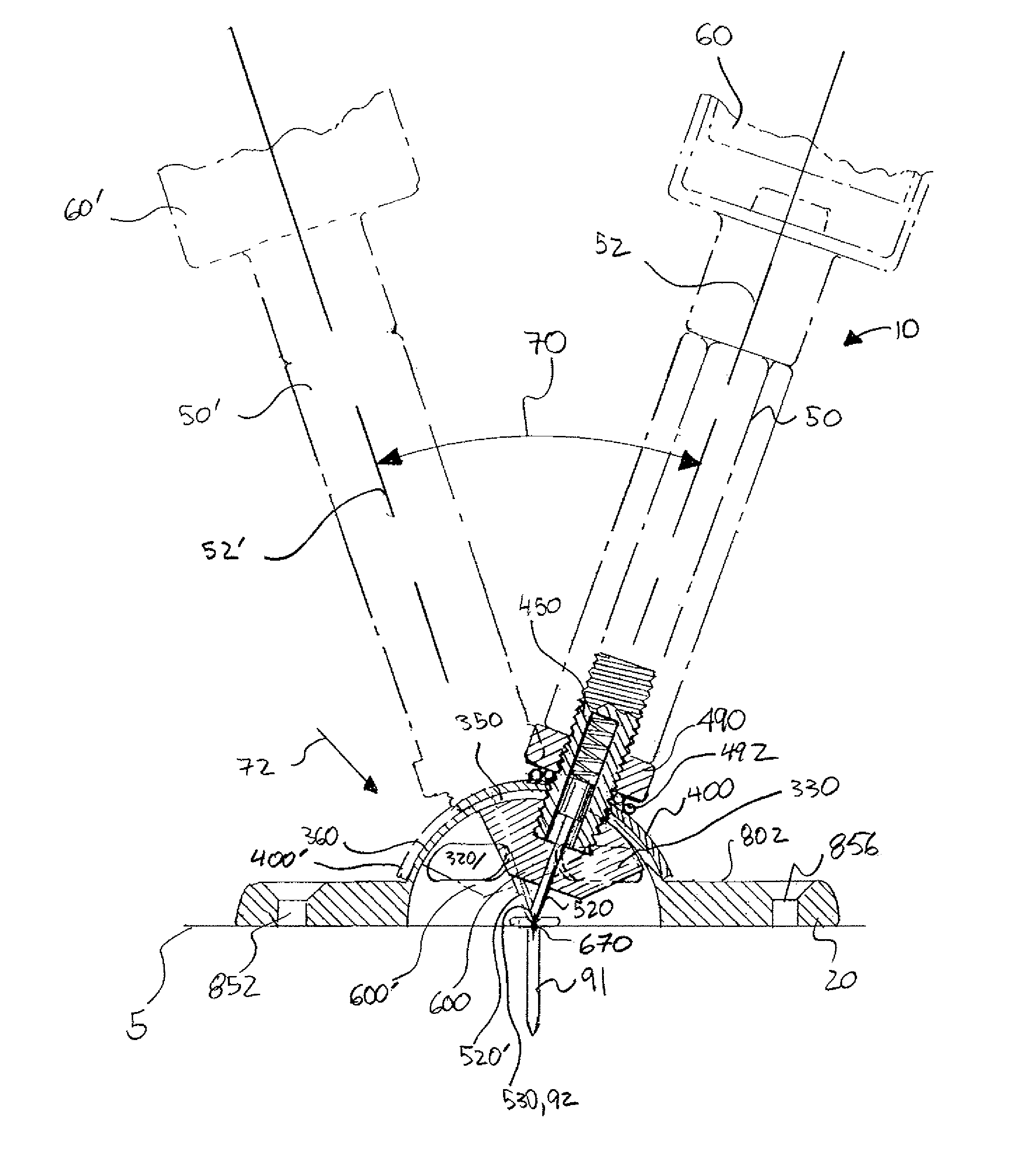
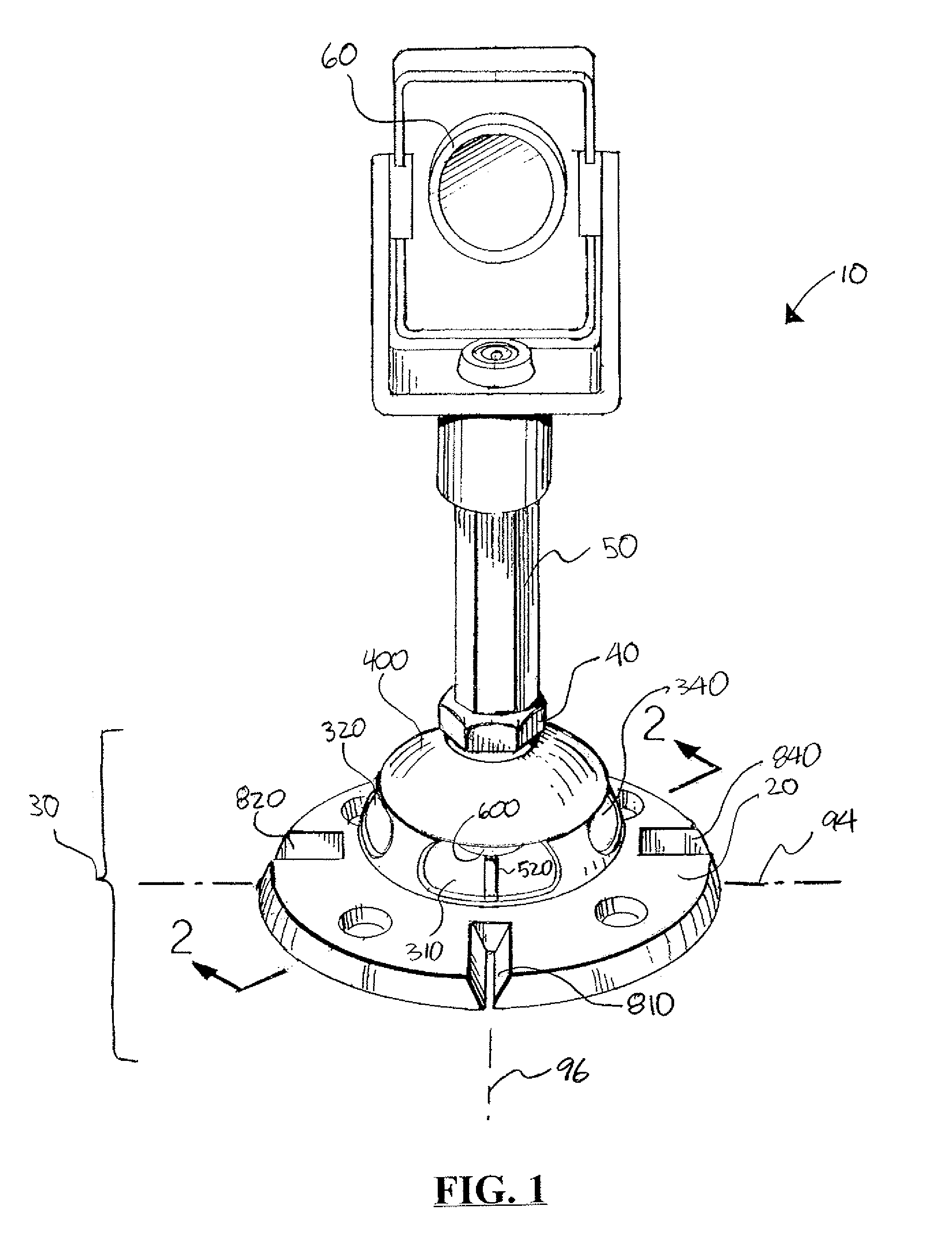
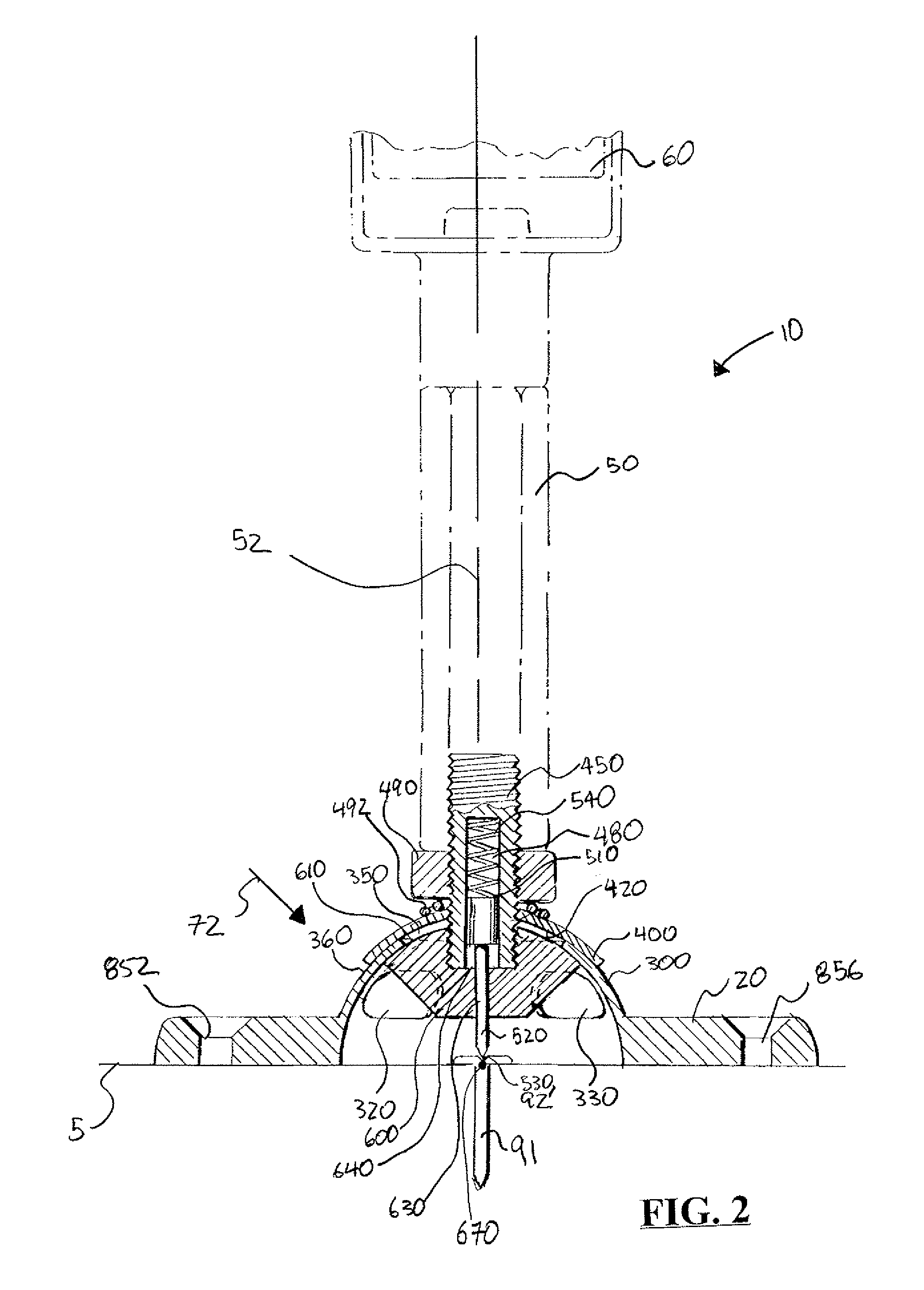
[0029]FIG. 1 is a perspective view of a preferred embodiment of an adjustable prism stand / pole 10. FIG. 2 is sectional view of adjustable stand 10 taken along the lines 2-2. FIG. 3 is an exploded perspective view of adjustable stand 10. FIG. 4 is a section view of adjustable stand 10 showing two possible positions for adjustment.

[0030]Using adjustable stand 10 allows pole 50 (and prism 60) to be adjustable at various angles relative to base 20. At a plurality of angles base 20 is placed, pole 50 can be adjusted so it points to Earth's center (an...


PUM


Abstract

In one embodiment is provided an adjustment mechanism wherein the surveying pole moves about a point which is located next to or adjacent the ground surface point at which the pole is being place. In one embodiment the surveying pole moves about a point which located at the ground surface. In one embodiment the surveying pole moves about a point which is located next to the ground surface, but above the ground surface. In one embodiment the surveying pole moves about a point which is located next to the ground surface, but below the ground surface. In one embodiment a tightening means is provided which is concentrically mounted around an axial line passing through the pole. In one embodiment a biasing means is operatively connected to the tightening means. In one embodiment the biasing means is a spring. In one embodiment the biasing means is a conical spring. In various embodiments the biasing means can be a spring chosen from the group consisting of helical, cylindrical, ellipitic, flat-leaf, leaf, rectangular plate, semielliptic, sprial-coiled. In one embodiment is provided at least one viewing window for the stand to be accurately placed. In one embodiment a plurality of windows are provided. In one embodiment four windows are provided which are radially spaced. In one embodiment is provided a pin is provided which can be used to accurately place the stand. In one embodiment the pin is slidingly attached to the stand and biased toward the center of rotation of the surveying pole.

Description

CROSS-REFERENCE TO RELATED APPLICATIONS[0001]Priority of U.S. Provisional Patent Application Ser. No. 60 / 761,545, filed Jan. 23, 2006, incorporated herein by reference, is hereby claimed.STATEMENT REGARDING FEDERALLY SPONSORED RESEARCH OR DEVELOPMENT[0002]Not applicableREFERENCE TO A “MICROFICHE APPENDIX”[0003]Not applicableBACKGROUND[0004]This invention relates generally to surveying equipment. Surveying equipment and particularly the support structure should be able to withstand all kinds of environmental conditions while retaining its integrity and dimensional accuracy. In many instances, the dimensional accuracy is imperative in order to obtain the correct measurements in a geographic survey. For instance, prism poles and global positioning satellite (GPS) poles should be able to retain a substantially fixed position of extension as they are moved from place to place over uneven terrain and in all kinds of weather.[0005]Prior art prism poles generally include two or more interfi...

Claims


Application Information

Patent Timeline
Patent Type & Authority Patents(United States)
IPC IPC(8): G01C15/02
CPCG01C15/02
Inventor CARAZO, KENNETH
Owner CARAZO KENNETH
Why Eureka
Try Eureka