Miter saw having holder fixing mechanism

a technology of fixing mechanism and miter saw, which is applied in the field of miter saw, can solve the problems of reducing workability, reducing the working space for changing the pivot posture, and affecting the operation of the clamp lever

Active Publication Date: 2010-03-02
KOKI HLDG CO LTD
View PDF24 Cites 16 Cited by
  • Summary
  • Abstract
  • Description
  • Claims
  • Application Information

AI Technical Summary

Benefits of technology

[0010]It is an object of the present invention to overcome the above-described problem and to provide a miter saw with a laterally tiltable circular saw blade capable of enhancing operability in a reducing a working space for changing pivot posture of the holder.

Problems solved by technology

If a wall or an object exists nearby the rear side of the holder, access to the clamp lever becomes impossible, thereby disabling the change in pivot posture of the holder.
This movement may lower the workability.
This drawback becomes apparent in case of a miter saw having a slide mechanism.
This degrades the workability.
However, the operation member must span between the holder and the front side of the base section, thereby increasing a length of the operation member.
This leads to an increase in weight and production cost.
Due to the elongated length of the operation member, excessive rotation force must be imparted on the operation member for clamping the pivot posture.
In order to avoid this problem, a diameter of the operation member must be increased, which in turn leads to increase in weight and production cost.
Further, since the operation member spans over a wide range, a degree of design freedom must be limited in designing the miter saw.

Method used


Image

  • Miter saw having holder fixing mechanism
  • Miter saw having holder fixing mechanism
  • Miter saw having holder fixing mechanism

Examples


first embodiment

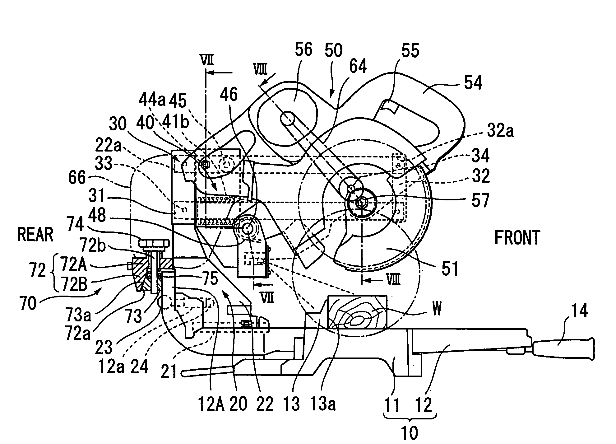
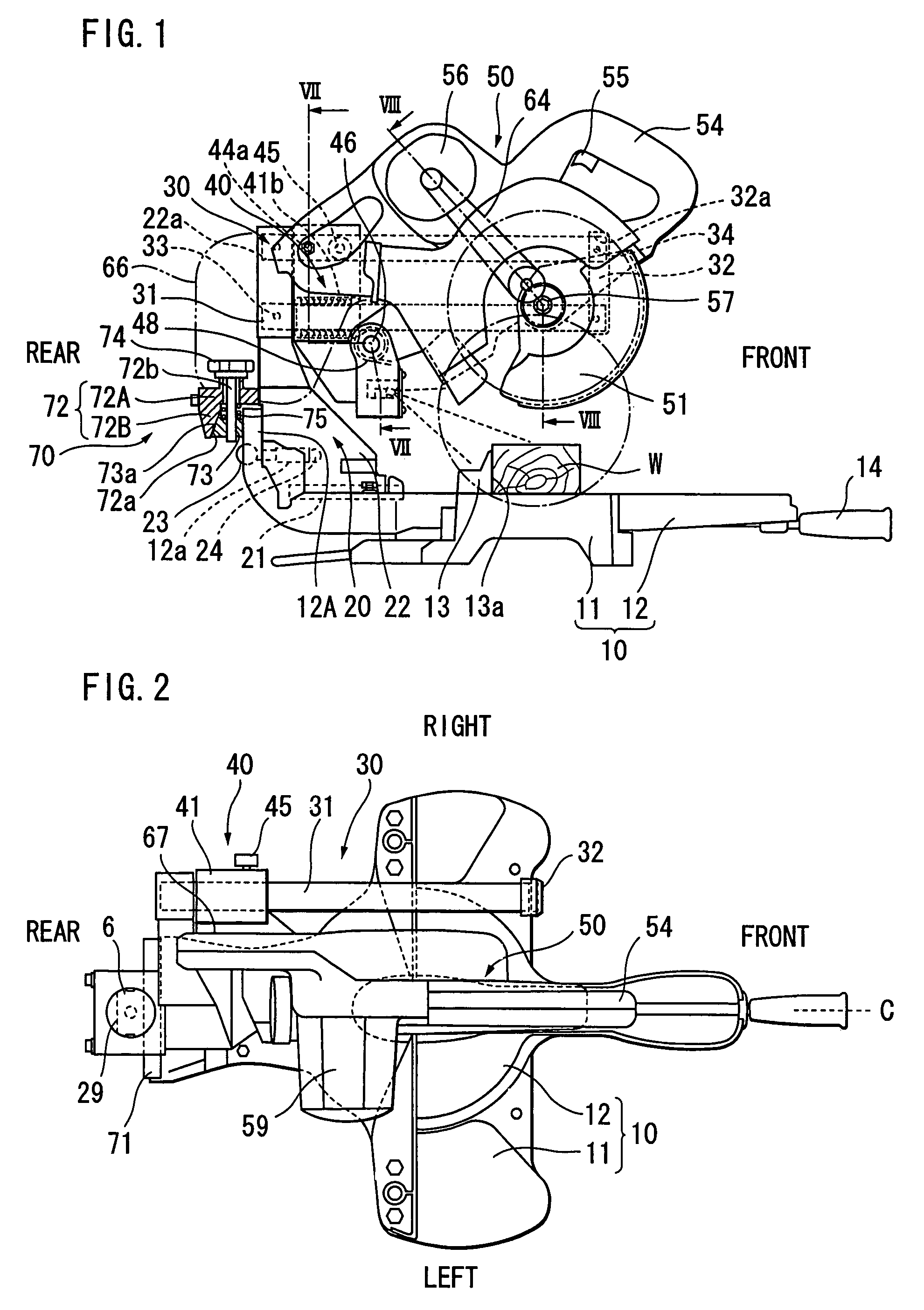
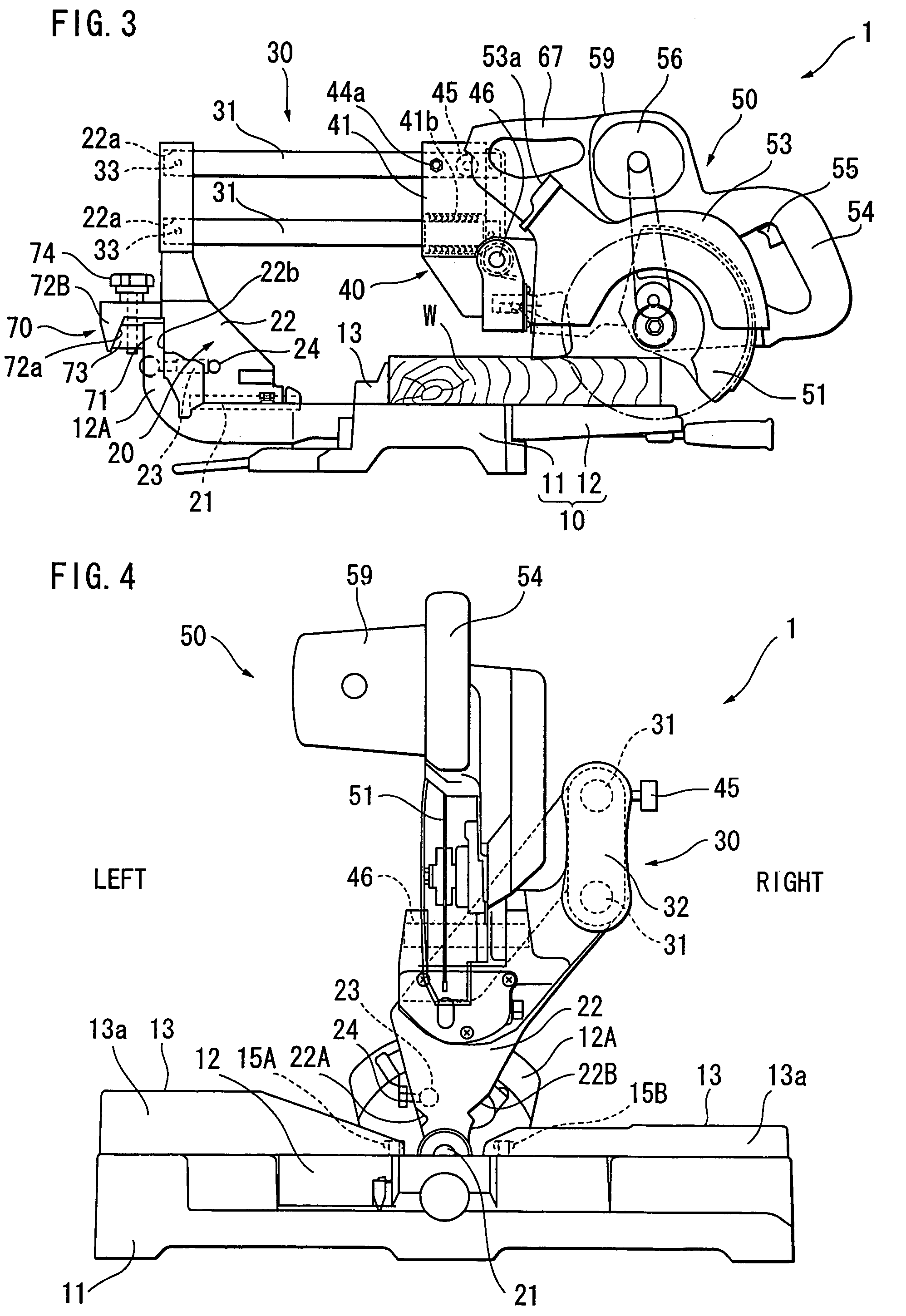
[0030]A miter saw having a mechanism for laterally tilting a circular saw blade according to the present invention will be described with reference to FIGS. 1 through 9. Unless otherwise noted, orientation terms, such as left, right, front, rear, up, and down, are used with respect to the normal orientation of the device for normal use. As shown in FIGS. 1 through 3, a miter saw 1 generally includes a base section 10, a guide bar support section 20, a guide bar section 30, a saw blade support section 40, and a saw blade section 50.

[0031]The base section 10 is adapted for mounting thereon a workpiece W to be cut. The guide bar support section 20 extends upwardly from the base section 10 and is pivotally supported to the base section 10 and tiltable laterally as shown in FIGS. 4 through 6. The guide bar section 30 is fixed to the guide bar support section 20 and extends in a horizontal and frontward / rearward direction. The saw blade support section 40 is supported on the guide bar sup...

sixth embodiment

[0090]A miter saw having a holder fixing mechanism according to the present invention is shown in FIG. 17 wherein like parts and components are designated by the same reference numerals as those shown in FIGS. 1 through 9 but added with 500. In the holder fixing mechanism 570, a component corresponding to the slider 73, 173, 273, 373, 473 is not provided. Instead, an arcuate protruding portion 572 protrudes from the upstanding portion 512A of the turntable 512. The arcuate protruding portion 572 is on an imaginary circle whose center is coincident with the axis of the pivot shaft 521. The arcuate protruding portion 572 is formed with a female thread 572a.

[0091]The holder 522 has a rearmost arcuate portion 522A positioned immediately above the arcuate protruding portion 572. The rearmost arcuate portion 522A is on an imaginary circle whose center is coincident with the axis of the pivot shaft 521. Further, an arcuate slot 522a is formed in the rearmost arcuate portion 522A. The clam...


PUM


Abstract

A miter saw having a holder fixing mechanism for fixing a pivot posture of a holder. The holder supports a support section on which a saw blade section is pivotally movably supported. The holder is laterally pivotally movable about a holder shaft to change angle of a side surface of a circular saw blade relative to an upper surface of a base. The holder fixing mechanism includes a clamp bolt whose axis is directed perpendicular to the holder shaft and in parallel with the side surface of the circular saw blade. By the rotation of the clamp bolt about its axis, a fixing relationship between the holder and the base section is established.

Description

BACKGROUND OF THE INVENTION[0001]The present invention relates to a miter saw having a circular saw blade section pivotable about a first axis extending in a direction parallel with a rotation axis of the circular saw blade, and pivotally movable about a second axis extending horizontally and in a direction perpendicular to the rotation axis.[0002]Japanese Patent Application Publication No. H11-254401 discloses a miter saw including a holder supporting a saw blade section having a circular saw blade. The saw blade section is pivotally movable toward and away from a base section about a first axis extending in a direction parallel with a rotation axis of the circular saw blade. The holder is pivotally movable about a holder shaft having a second axis extending horizontally along an upper surface of the base section and in a direction perpendicular to the rotation axis. Thus, the saw blade section is tiltable leftward and rightward about the holder shaft.[0003]A clamp lever also exten...

Claims


Application Information

Patent Timeline
Patent Type & Authority Patents(United States)
IPC IPC(8): B27B5/20B23D45/04B23D45/14B23D47/02B27B3/12B27B5/29B27B19/00
CPCB27B5/29Y10T83/7697Y10T83/7705Y10T83/7726Y10T83/7772Y10T83/7788Y10T83/853Y10T83/8773
Inventor IMAMURA, RYUICHIUSHIWATA, SHIGEHARU
Owner KOKI HLDG CO LTD
Why Eureka
Try Eureka