Magnet type rodless cylinder

a rodless cylinder, magnet-type technology, applied in the direction of cylinders, reciprocating piston engines, positive displacement engines, etc., can solve the problems of inability to put magnet-type rodless cylinders with non-circular cylinder holes into practical use, excessive stress and maximum deflection of tubes, and tube non-uniform deformation, etc., to achieve easy formation, reduce the size of the apparatus, and reduce the effect of tube thrus

Active Publication Date: 2010-03-02
HOWA MASCH LTD
View PDF9 Cites 0 Cited by
  • Summary
  • Abstract
  • Description
  • Claims
  • Application Information

AI Technical Summary

Benefits of technology

[0032]In view of the above problems of the related art as described above, an object of the present invention is to provide a practical magnet-type rodless cylinder, which has a plurality of cylinder tubes arranged in parallel with each other and capable of preventing a decrease in durability and thickness (height) of the rodless cylinder as a whole by adjusting the repulsive forces acting between the pistons.

Problems solved by technology

Therefore, if internal pressure is excerted by the fluid, the tubes undergo a non-uniform deformation.
When cylinder tubes having a non-circular shape in cross section are used, a stress concentration or partial deflection occurs on the tube, and both maximum stress and maximum deflection of the tube may become excessive.
Because of this, magnet-type rodless cylinders having cylinder holes of a non-circular shape are difficult to be put into practical use.
This causes an increase in the number of the assembling steps and an increase in the installation space of the cylinders.
This results in an increase in the minimum operation pressure of the working fluid required for moving the pistons when supplying the working fluid into the cylinder.
An increase in the minimum operation pressure of the working fluid causes a problem of decreased durability at various portions of magnet-type rodless cylinders.

Method used


Image

  • Magnet type rodless cylinder
  • Magnet type rodless cylinder
  • Magnet type rodless cylinder

Examples


Embodiment Construction

[0052]An embodiment of the magnet-type rodless cylinder of the invention will now be explained with reference to the attached drawings.

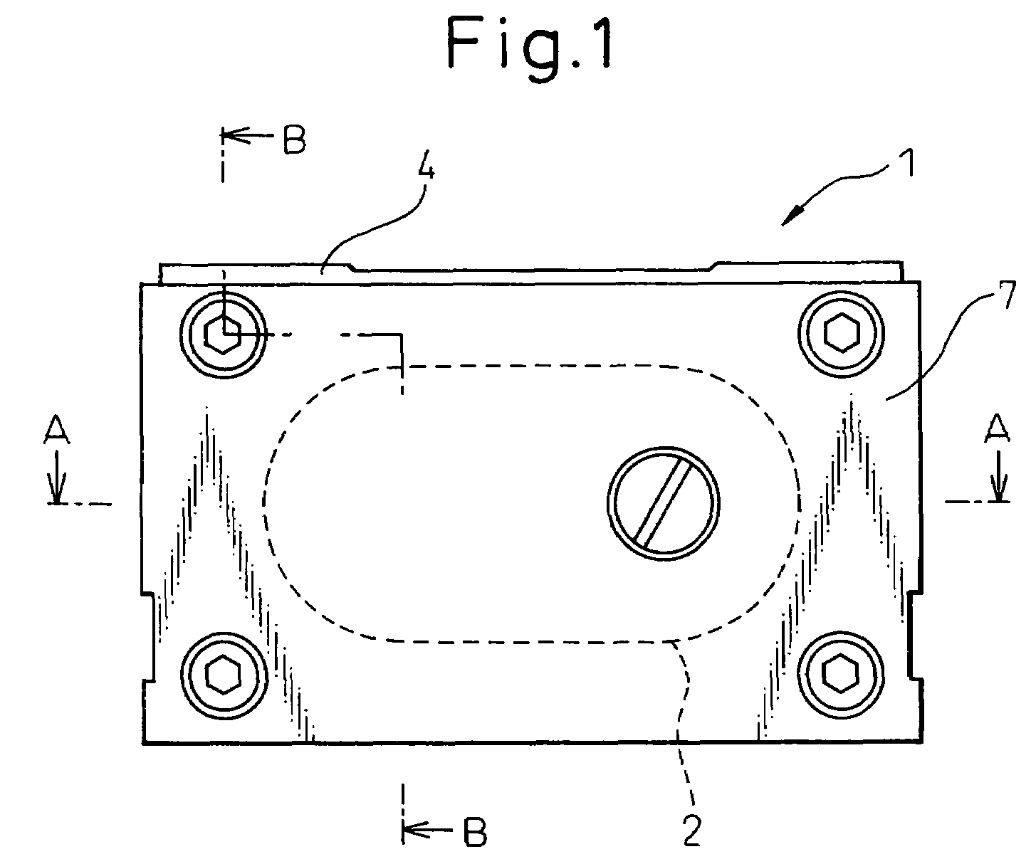
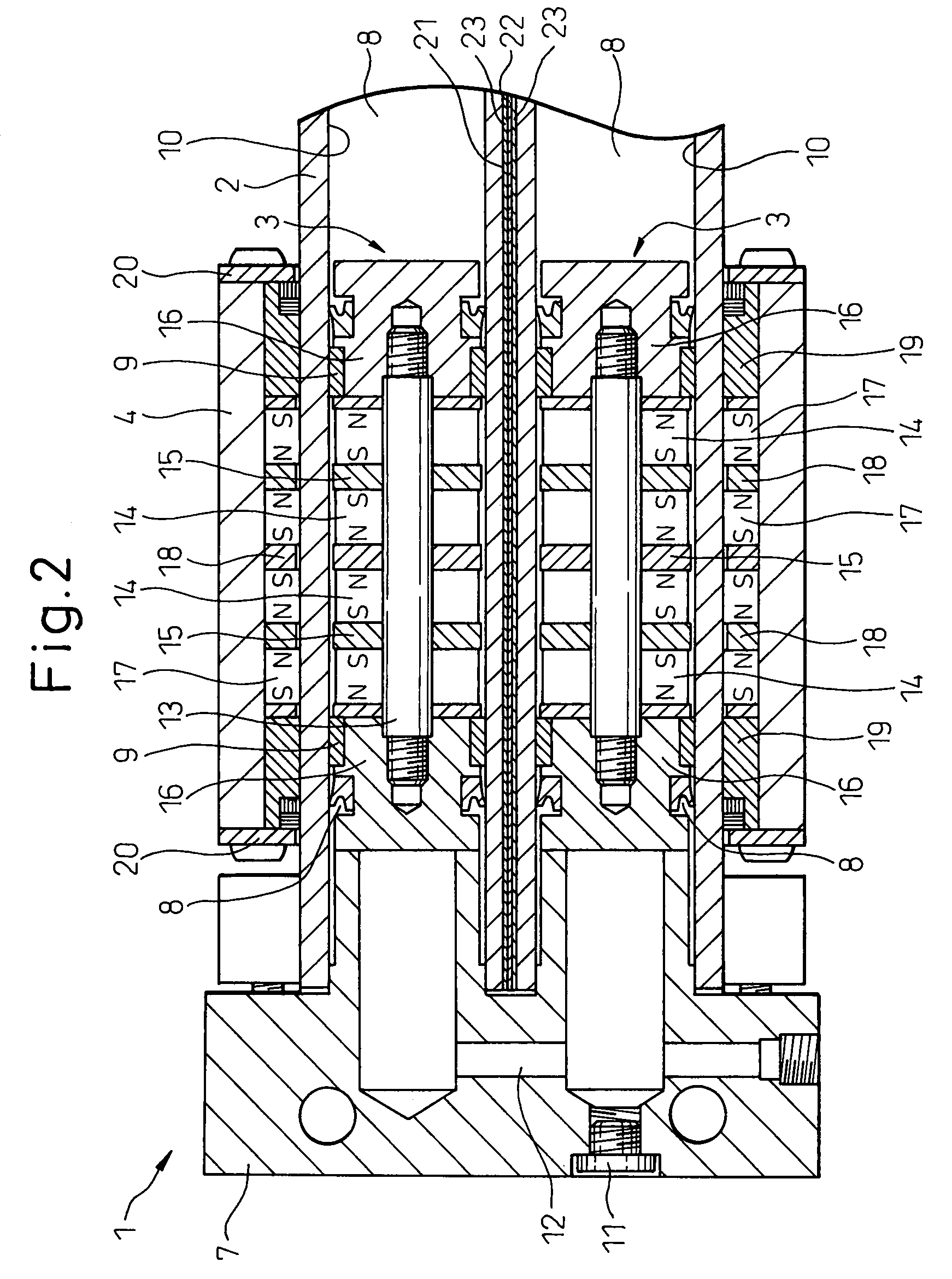
[0053]FIG. 1 is a front view of a magnet-type rodless cylinder 1, FIG. 2 is a sectional view along line A-A in FIG. 1, FIG. 3 is a sectional view along line B-B in FIG. 1 and FIG. 4 is a sectional view along line C-C in FIG. 3.

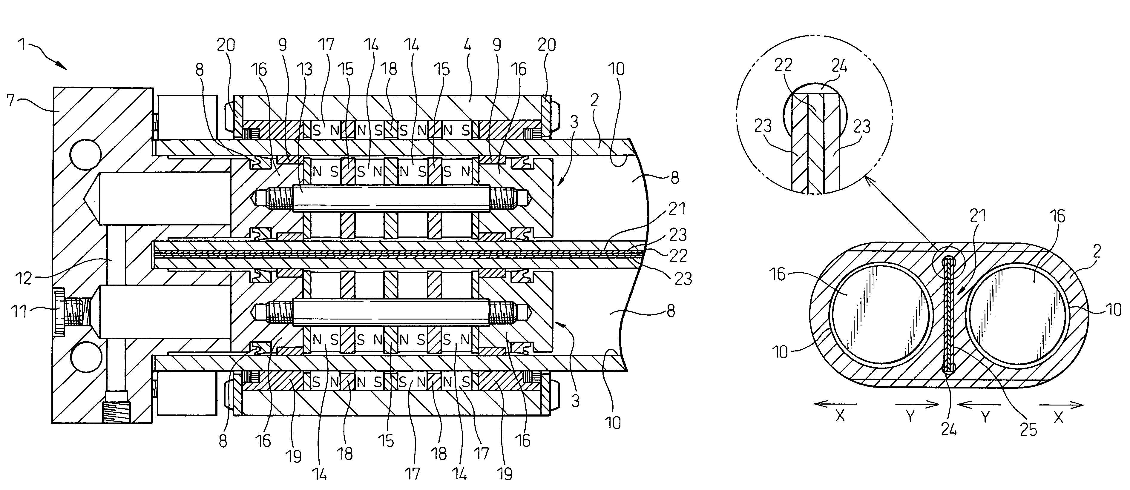
[0054]As shown in FIG. 3, the magnet-type rodless cylinder 1 of this embodiment includes a cylinder tube 2 made of a nonmagnetic material disposed between end caps 7 and 7. A slider 4 of a rectangular shape in cross section is provided on the outer circumference of the cylinder tube 2 to slide in the axial direction of the cylinder tube 2.

[0055]The cylinder tube 2 has a flat elliptic shape in cross section as shown in FIG. 4. The cylinder tube 2 is disposed so that it penetrates through the slider 4, and therefore, the slider 4 is guided along the axis of the cylinder tube 2 while maintaining its horizontal state.

[0056]Further,...


PUM


Abstract

A pair of cylinder holes 10 are formed in a cylinder tube 2 in the axial direction, a slit 25 is formed between these cylinder holes, and an iron plate 22 is inserted in the slit covering the whole range of the movement of the pistons 3 in the cylinder holes. Spacers 23 made of a synthetic resin are interposed on both sides of the iron plate 22 to reliably hold the iron plate 22 in the slit 25. The iron plate 22 disposed between the cylinder holes works to decrease the repulsive force acting between the inner magnets 14 of the pistons and produce an attracting force between the iron plate 22 and the inner magnets 14, and a contact surface pressure between the wear rings 9 of the pistons 3 and the wall surfaces of the cylinder holes 10 can be adjusted to a suitable value.

Description

TECHNICAL FIELD[0001]The present invention relates to a magnet-type rodless cylinder having a plurality of cylinder holes in a cylinder tube.BACKGROUND ART[0002]A magnet-type rodless cylinder provided with cylinder holes formed in a cylinder tube, pistons disposed in the cylinder holes so as to move therein, and a slider disposed on the outer side of the cylinder tube and moves along the outer circumference of the cylinder tube, the pistons and the slider being magnetically coupled together, is known in the art.[0003]In magnet-type rodless cylinders, generally, magnets (inner magnets) are arranged in the pistons and magnets (outer magnets) or magnetic material are arranged on the slider. Due to the attracting forces exerted between these magnets and / or magnetic material, the pistons and the slider are magnetically coupled together, and the slider follows the movement of the pistons.[0004]There is known a magnet-type rodless cylinder having a plurality of cylinder holes and a plurali...

Claims


Application Information

Patent Timeline
Patent Type & Authority Patents(United States)
IPC IPC(8): F01B29/08
CPCF15B15/086F15B15/1447F15B15/1466Y10S91/04F15B15/14
Inventor HORIKAWA, AKIYOSHIMINOWA, NAOKIYOSHIDA, HIROSHINODA, MITSUO
Owner HOWA MASCH LTD
Why Eureka
Try Eureka