Multiple function geomatics pole support device

a geomatics pole and multi-functional technology, applied in the field of multi-functional geomatics pole support devices, can solve the problems of inconvenient handheld positioning of geomatics poles, inconvenient use of wall mounted level vial checking devices, and inaccuracy of measurements

Active Publication Date: 2010-03-02
SECO MFG CO INC +1
View PDF71 Cites 14 Cited by
  • Summary
  • Abstract
  • Description
  • Claims
  • Application Information

AI Technical Summary

Problems solved by technology

For one, the level indication vials of these poles often lose their accuracy calibration, which may cause inaccurate measurements.
Thus, these wall mounted level vial checking devices are not available for use in the field.
However, the practice of handheld positioning of geomatics poles also has disadvantages.
One of these disadvantages is that precise and extended retention of pole position is very difficult.
Therefore, measurements taken with handheld poles are less precise than supported ones.
Another disadvantage with handheld poles becomes evident when a surveyor must perform a task not involving the pole, such as installing a monument or making a note.
In these instances, the pole is often laid directly on the ground, subjecting the pole and target to damage and malfunction as a result of ground borne debris (e.g., sand, mud).
These pole support devices have disadvantages, among which is that they only perform one function.
Additionally, these tripods are slow and difficult to set up with targets because the procedures for establishing precise vertical collimation, and determination of height of targets, are quite time consuming.
Dedicated target tripods have an additional disadvantage of performing only one function.
The disadvantages of using tripods for geomatic target supports often limit their use to those measurements requiring great accuracy.
These types of support devices also have many disadvantages, such as being capable of only one use; providing a pole to tripod interface.
Also, the positive coupling connections found in many of these pole supports tend to inhibit free rotation of the poles, which inhibits level vial calibration confirmations.
Additionally, these pole supports tend to be complex in design, heavy, and expensive.
However, this pole support also has disadvantages, one of which is that the captivity of the geomatics pole is rather flimsy, as the pole is retained with an elastic band.
Additionally, the elastic band must be manually attached and detached when the geomatics pole is installed and removed, which is inconvenient and also requires two hands to perform.
Additionally, in order to prevent friction and thus permit free sliding and rotation of the pole, the elastic band must be rather weak in design, which may cause the pole to be unstable and possibly result in inaccurate measurements.
Additionally, the force of wind can critically load the elastic band allowing the geomatics pole to fall to the ground thereby subjecting the pole, the level vial and its geomatics target to damage.
The exposure of survey equipment to ground borne debris such as mud or sand can render the equipment inaccurate or even inoperable.

Method used


Image

  • Multiple function geomatics pole support device
  • Multiple function geomatics pole support device
  • Multiple function geomatics pole support device

Examples


Embodiment Construction

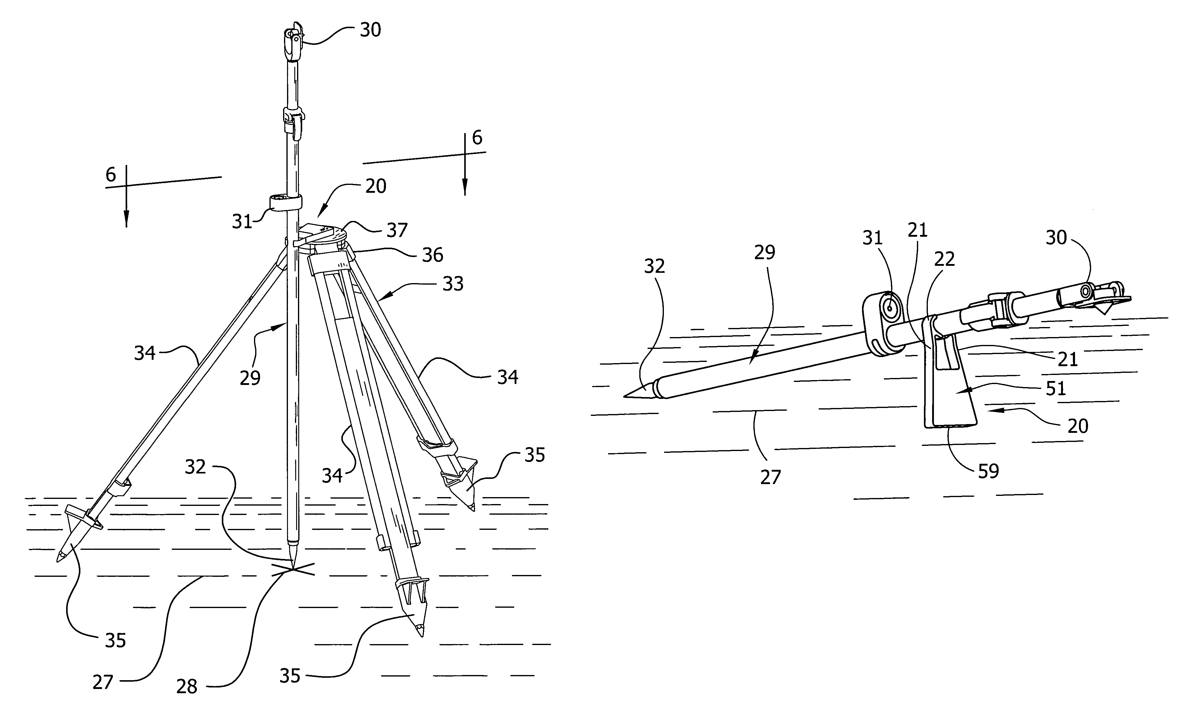
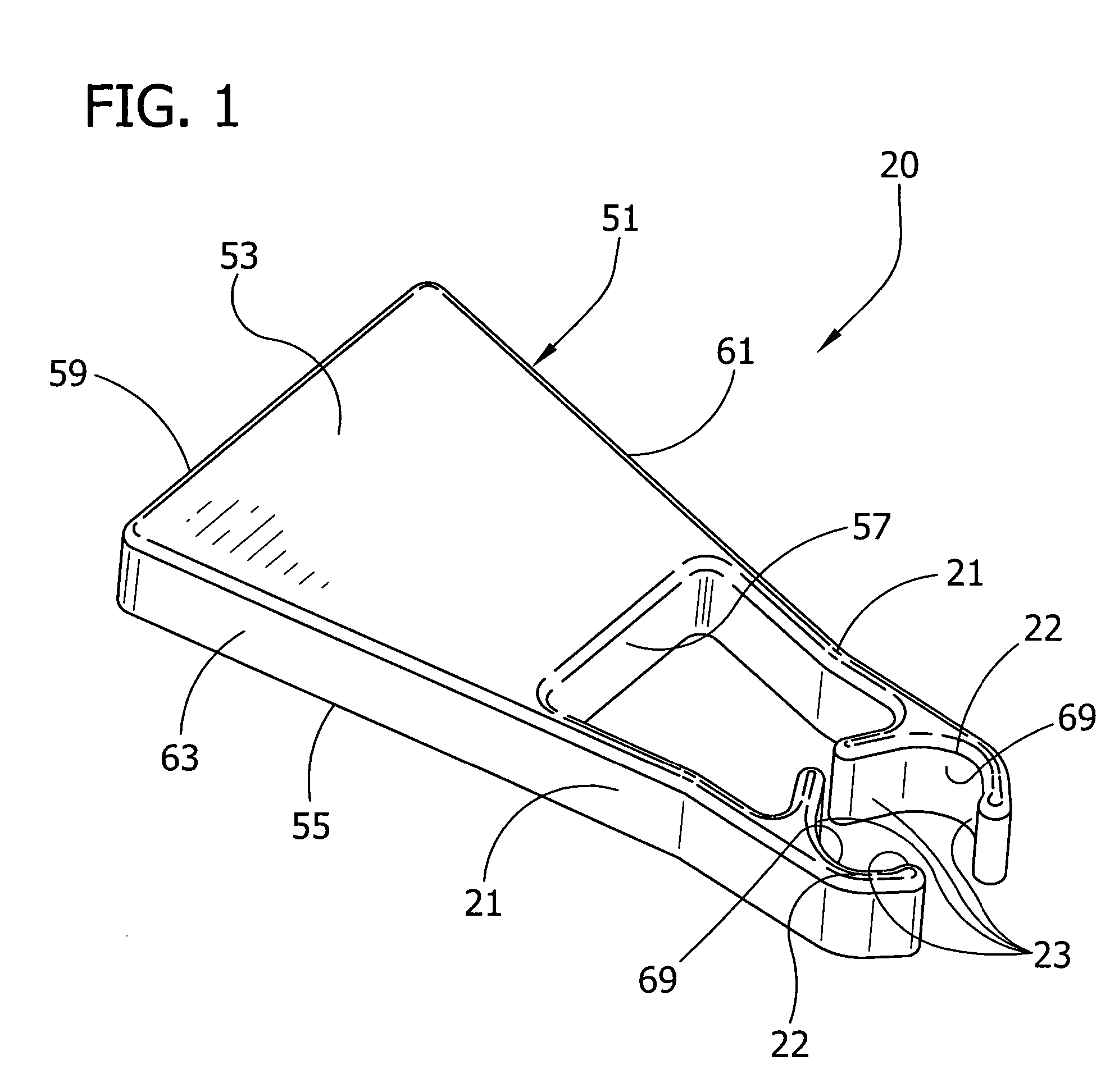
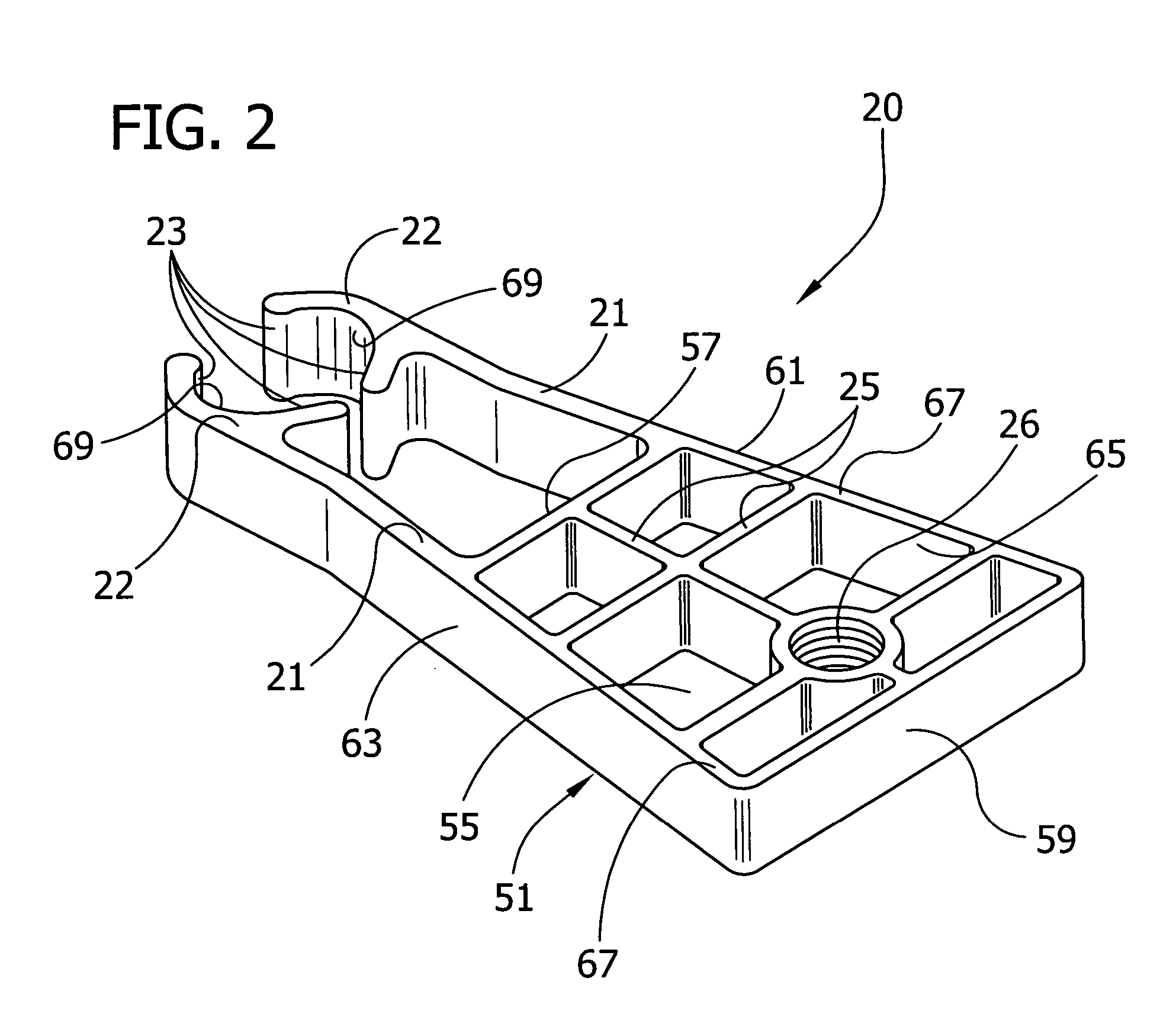
[0027]The geomatics pole support device, generally indicated at 20, of the present invention is shown in FIGS. 1 and 2. The pole support device 20 comprises a body, generally indicated at 51, and bifurcated jaw support arms 21 extending outwardly from the body. In the illustrated embodiment, the body 51 has a top 53, a bottom 55 and four sides 57, 59, 61, 63. The top 53 of the body 51 has a generally flat surface with beveled edges along its periphery. The four sides 57, 59, 61, 63 of the body, which generally form an isosceles trapezoid, extend downward (as the device is viewed in FIG. 1) from the periphery of the top 53 of the body 51. Accordingly, the body 51 has a front 57, a back 59, a right side 61 and a left side 63. The front and back 57, 59 of the body 51 are generally parallel but have different lengths. The back 59 is longer than the front 57. The right and left sides 63, 61 have approximately the same lengths but are not parallel. It is understood that the body 51 of the...


PUM


Abstract

A geomatics pole support comprises a body and pole engaging members for connecting the support to a geomatics pole so that the body is retained by the pole engaging members projecting generally laterally outwardly from a longitudinal axis of the pole. The body further includes a terrain engagement surface adapted to engage a ground surface and to hold at least a portion of the pole in a stable position out of contact with the ground surface.

Description

CROSS REFERENCE TO RELATED APPLICATION[0001]This application claims the benefit of U.S. Provisional Application No. 60 / 536,468, filed Jan. 13, 2004.BACKGROUND OF THE INVENTION[0002]This invention relates generally to devices which support various surveying and geomatics poles, and more particularly to a support suitable for steading poles during measurements, permitting calibration verification of leveling indication vials, and holding a portion of the pole out of contact with the ground.[0003]During a typical survey, multiple and various measurements are often taken requiring varies degrees of accuracies. For example, measurements of property boundaries may require a greater degree of accuracy than measurements locating the position of fire hydrants, yet both measurements may be performed in the same survey using the same geomatics target device. In order to meet the specific accuracy or speed efficiency requirements of a particular measurement, survey crew members may be required ...

Claims


Application Information

Patent Timeline
Patent Type & Authority Patents(United States)
IPC IPC(8): F16M11/32G01C15/06
CPCG01C15/06
Inventor CRAIN, STEPHEN B.MOORE, CHRISTOPHER T.
Owner SECO MFG CO INC
Why Eureka
Try Eureka