Method and system for identifying illumination flux in an image

a technology of illumination flux and image, applied in the field of images, can solve the problems of not being able to recognize objects by computers, not being able to process images in other directions, and significant possibilities for false positives and false negatives for shadow recognition, etc., to achieve accurate and correct reflection and representation

Active Publication Date: 2010-03-02
INNOVATION ASSET COLLECTIVE
View PDF18 Cites 52 Cited by
  • Summary
  • Abstract
  • Description
  • Claims
  • Application Information

AI Technical Summary

Benefits of technology

[0004]The present invention provides a method and system comprising image techniques that accurately and correctly reflect and represent physical phenomena occurring in the visual world.

Problems solved by technology

A challenge in the utilization of computers to accurately and correctly perform operations relating to images is the development of algorithms that truly reflect and represent physical phenomena occurring in the visual world.
For example, the ability of a computer to correctly and accurately distinguish between a shadow and a material object edge within an image has been a persistent challenge to scientists.
Edge detection is a fundamental task in image processing because without accurate and correct detection of the edges of physical objects, no other processing of the image is possible.
If a cast shadow is indistinguishable from the object casting the shadow, it would not be possible for the computer to recognize the object.
While this approach can be implemented by algorithms that can be accurately executed by a computer, the results will often be incorrect.
Thus, when utilizing conventional techniques for shadow and edge recognition, there are significant possibilities for false positives and false negatives for shadow recognition.

Method used


Image

  • Method and system for identifying illumination flux in an image
  • Method and system for identifying illumination flux in an image
  • Method and system for identifying illumination flux in an image

Examples


Embodiment Construction

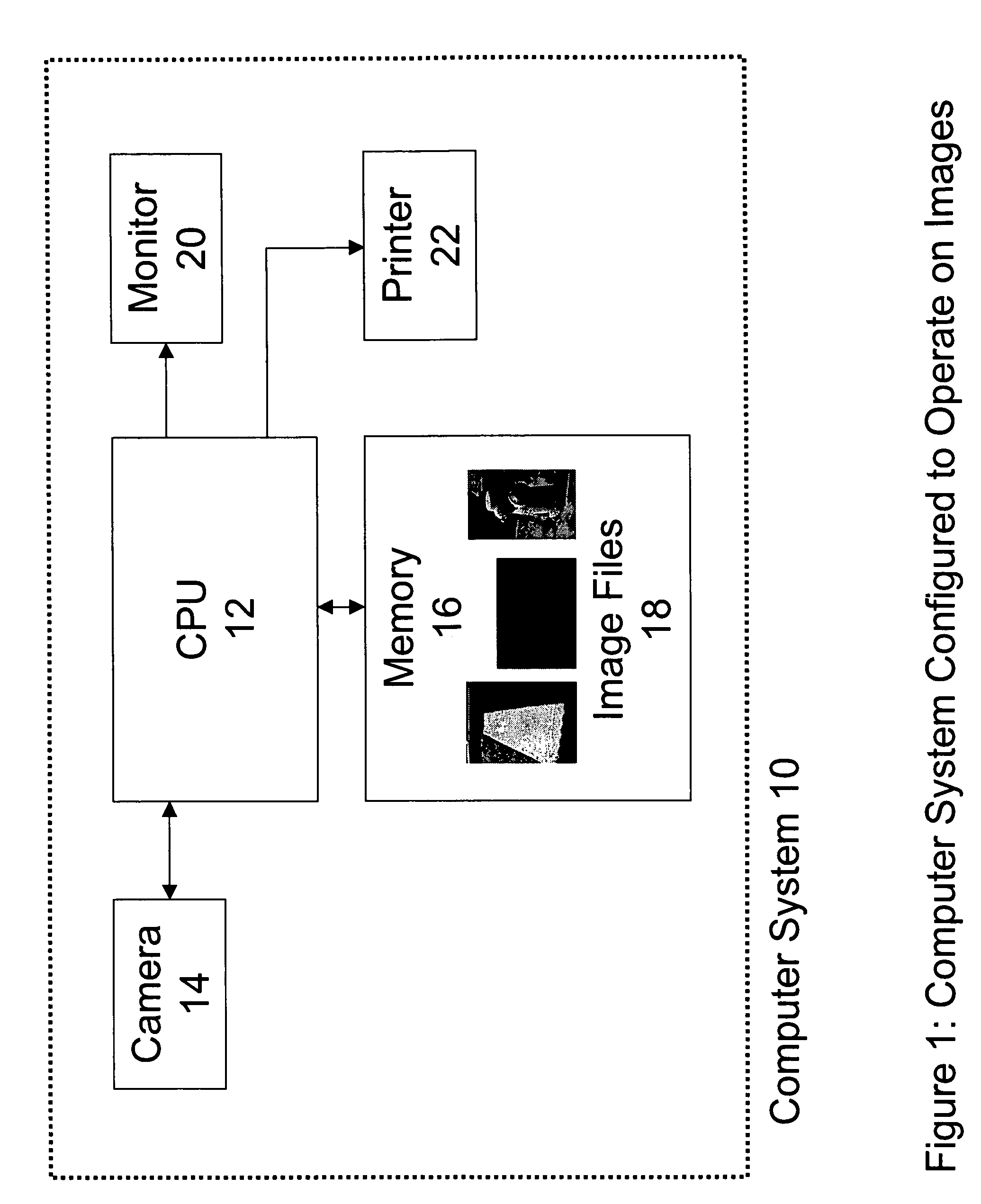
[0034]Referring now to the drawings, and initially to FIG. 1, there is shown a block diagram of a computer system 10 arranged and configured to perform operations related to images. A CPU 12 is coupled to a device such as, for example, a digital camera 14 via, for example, a USB port. The digital camera 14 operates to download images stored locally on the camera 14, to the CPU 12. The CPU 12 stores the downloaded images in a memory 16 as image files 18. The image files 18 can be accessed by the CPU 12 for display on a monitor 20, or for print out on a printer 22.

[0035]Alternatively, the CPU can be implemented as a microprocessor embedded in a device such as, for example, the digital camera 14 or a robot. The CPU can also be equipped with a real time operating system for real time operations related to images, in connection with, for example, a robotic operation or an interactive operation with a user.

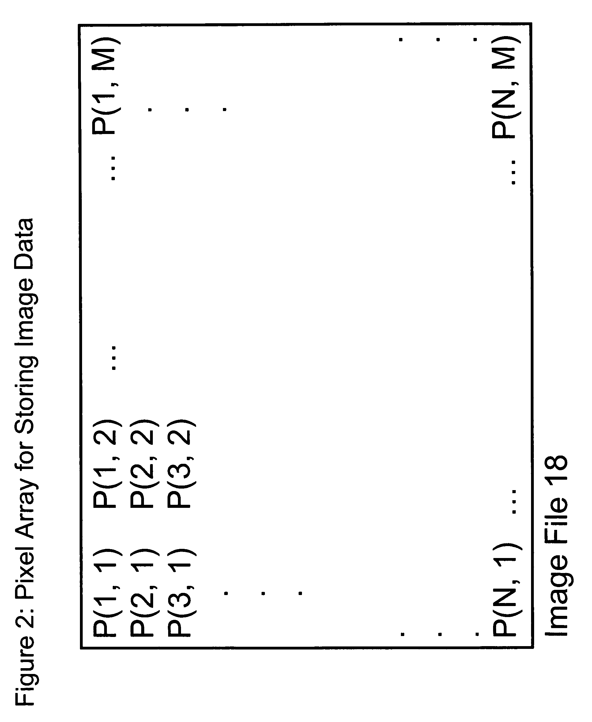
[0036]As shown in FIG. 2, each image file 18 comprises an n×m pixel array. Each pix...


PUM


Abstract

In a first exemplary embodiment of the present invention, an automated, computerized method is provided for determining an illumination boundary in an image. The method comprises the steps of performing dynamic sampling in preselected local areas of the image to determine spectral ratio information for the image at each of the preselected local areas, and utilizing the spectral ratio information to identify an illumination boundary.

Description

[0001]This application claims the benefit of U.S. Provisional Patent Application No. 60 / 648,228, filed Jan. 27, 2005, and U.S. Provisional Patent Application No. 60 / 650,300, filed Feb. 3, 2005, which are hereby incorporated by reference.BACKGROUND OF THE INVENTION[0002]Many significant and commercially important uses of modern computer technology relate to images. These include image processing, image analysis and computer vision applications. A challenge in the utilization of computers to accurately and correctly perform operations relating to images is the development of algorithms that truly reflect and represent physical phenomena occurring in the visual world. For example, the ability of a computer to correctly and accurately distinguish between a shadow and a material object edge within an image has been a persistent challenge to scientists. Edge detection is a fundamental task in image processing because without accurate and correct detection of the edges of physical objects,...

Claims


Application Information

Patent Timeline
Patent Type & Authority Patents(United States)
IPC IPC(8): G06K9/40G06V10/143G06V10/56G06V10/60
CPCG06K9/2018G06K9/346G06K9/4638G06K9/4652G06K9/4661G06T7/0083G06T7/12G06V10/143G06V10/273G06V10/457G06V10/60G06V10/56
Inventor FRIEDHOFF, RICHARD MARKMAXWELL, BRUCE ALLENSMITH, CASEY ARTHUR
Owner INNOVATION ASSET COLLECTIVE
Why Eureka
Try Eureka