Method of point source target detection for multispectral imaging

a multi-spectral imaging and target detection technology, applied in the field of optical sensors, can solve the problems of inability to account for the true background source, the method is vulnerable to corruption, and the complexity of detecting such signatures

Active Publication Date: 2014-01-09
BAE SYST INFORMATION & ELECTRONICS SYST INTERGRATION INC
View PDF7 Cites 4 Cited by
  • Summary
  • Abstract
  • Description
  • Claims
  • Application Information

AI Technical Summary

Problems solved by technology

Typically, detecting such signatures becomes more complex because the optical sensors often record many non-target, background sources of radiation, which can obscure a true threat signature.
However, this method is vulnerable to corruption if even just one or two pixels have aberrant radiant properties.
The vulnerability in the existing method stems from the inability to account for the true background sources.
Unfortunately, this method requires substantial processing power to apply the filter to each spectrum and this separated filtering may introduce noise into the image because the background source has not yet been removed.

Method used


Image

  • Method of point source target detection for multispectral imaging
  • Method of point source target detection for multispectral imaging
  • Method of point source target detection for multispectral imaging

Examples


Embodiment Construction

[0013]The exemplary embodiments described herein in detail for illustrative purposes are subject to many variations in structure and design.

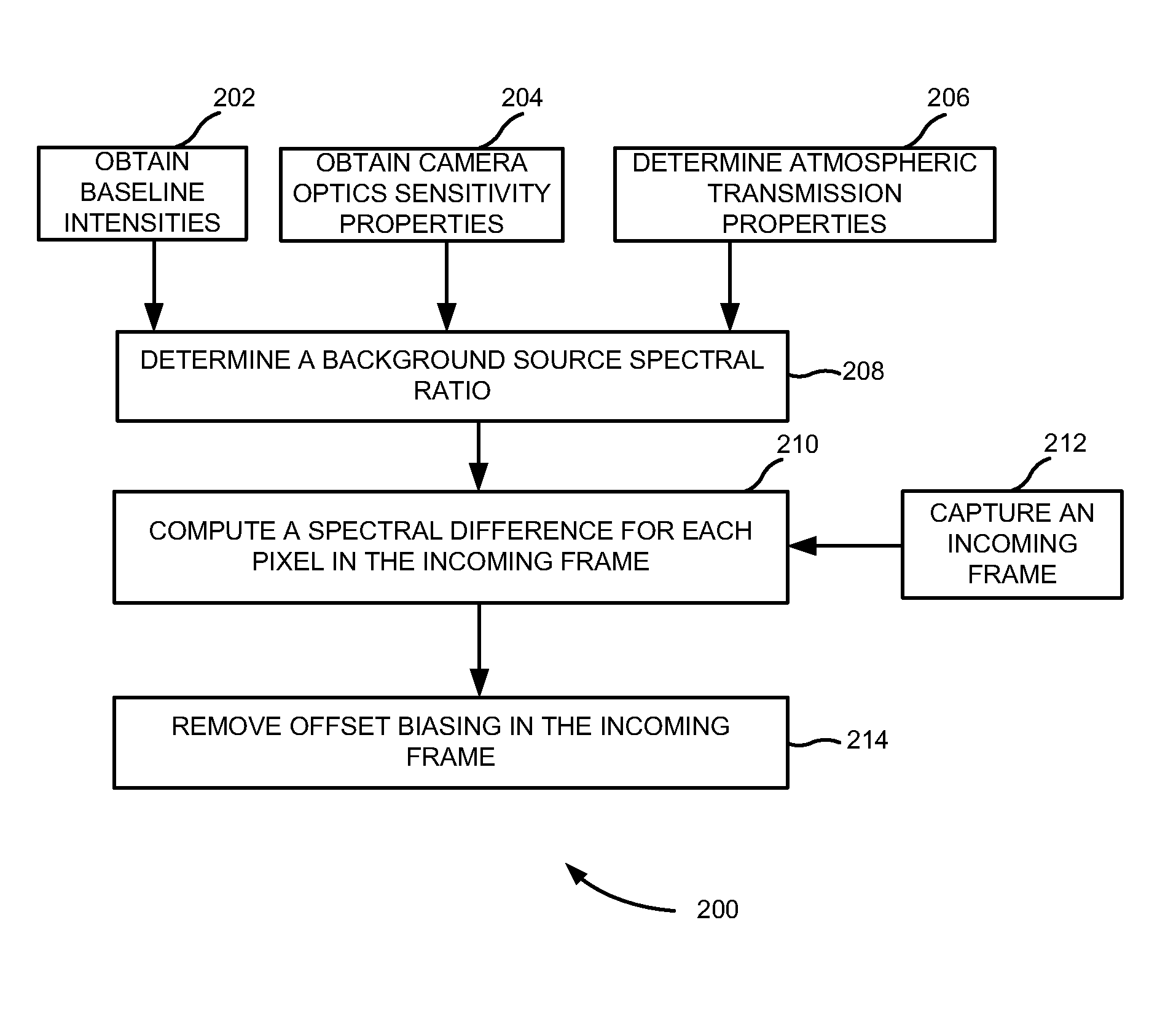
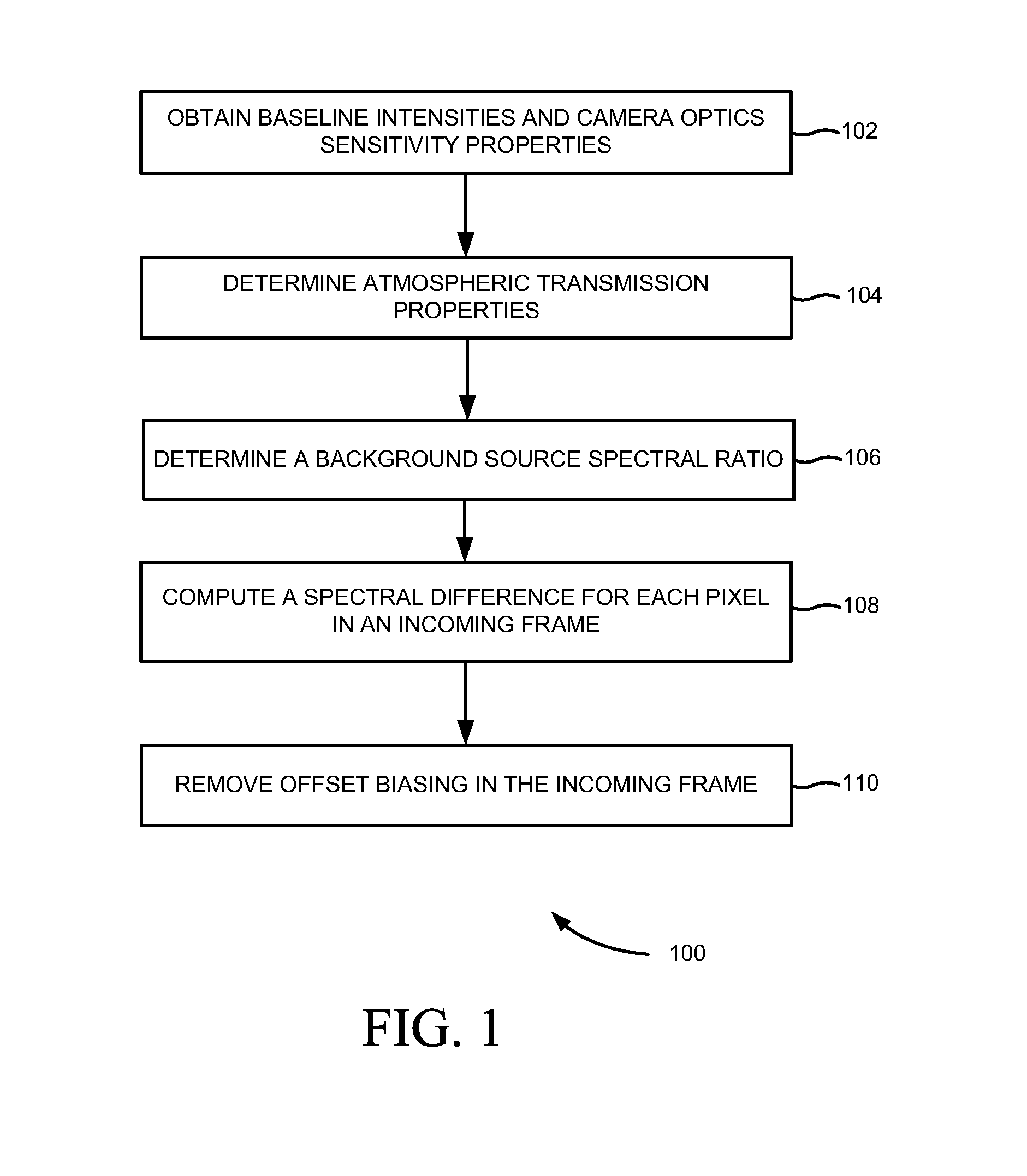
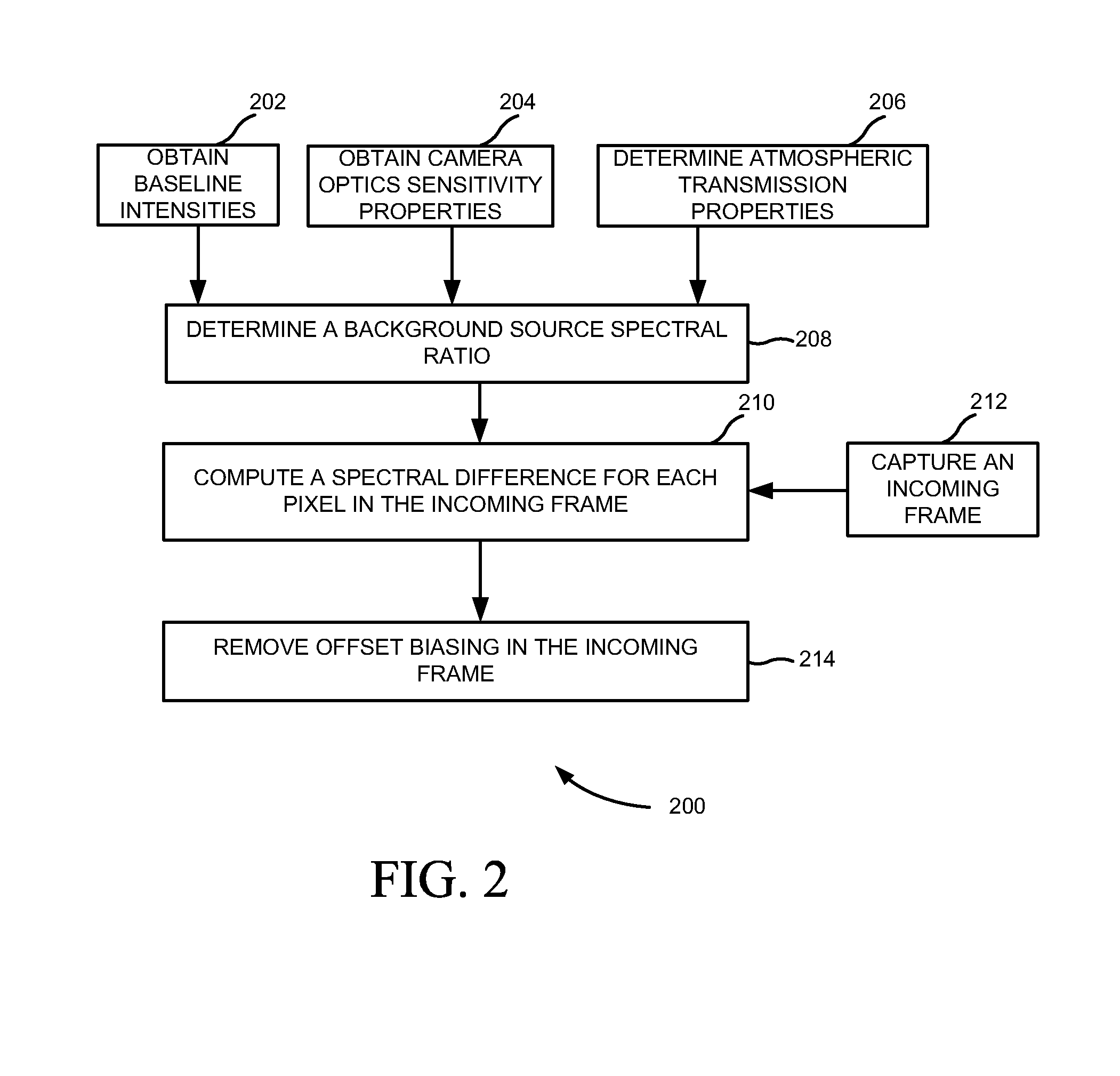
[0014]FIG. 1 illustrates a flowchart 100 of a method of point source target detection for multispectral imaging, according to an embodiment of the present subject matter. At block 102, baseline intensities and camera optics sensitivity properties of an optical sensor in spectral bands are obtained. For example, the baseline intensities are blackbody temperature of the earth and any other background temperature of a spectral image being viewed. At block 104, the atmospheric transmission properties of the spectral bands are determined as a function of a range to the pixel and atmospheric visibility conditions. At block 106, a background source spectral ratio is determined using at least one radiant source, such as the baseline intensities, camera optics sensitivity properties and atmospheric transmission properties.

[0015]At block 108, a spectral d...


PUM


Abstract

A method of point source target detection for multispectral imaging is disclosed. In one embodiment, a background source spectral ratio is determined using at least one radiant source, such as baseline intensities, camera optics sensitivity properties and atmospheric transmission properties. Further, a spectral difference is computed for each pixel in an incoming frame by applying the background source spectral ratio to a spectral band-specific radiant intensity value of each pixel. Furthermore, offset biasing in the incoming frame is removed by applying spatial median filtering to each computed spectral difference in the incoming frame.

Description

CROSS-REFERENCE TO RELATED APPLICATION[0001]This Application claims rights under 35 USC §119(e) from U.S. Application 61 / 506,195 filed Jul. 11, 2011, the contents of which are incorporated herein by reference.BACKGROUND OF THE INVENTION[0002]1. Field of the Invention[0003]The present invention relates to optical sensors, more specifically to multispectral target detection using optical sensors.[0004]2. Brief Description of Related Art[0005]One of the most common uses of optical sensors in a military setting is to detect and counter launched ordnance as part of a threat detection system. To achieve maximum protection of a host platform, it is crucial to rapidly detect a threat and accurately identify a type of the threat detected while minimizing use of processing resources. One way to achieve this end is by recognizing a spectral signature of a point source in an optical field of view (FOV).[0006]Each type of launched ordnance typically emits a signature consistent radiant intensity...

Claims


Application Information

Patent Timeline
Patent Type & Authority Applications(United States)
IPC IPC(8): G06K9/00G06V20/00G06V10/30
CPCG06K9/00624G06V20/194G06V20/00G06V10/30
Inventor MERCIER, MICHAELSCHLUPF, JOSEPH M.
Owner BAE SYST INFORMATION & ELECTRONICS SYST INTERGRATION INC
Why Eureka
Try Eureka