Shock absorbing structure

a technology of shock absorption and structure, which is applied in the field of shock absorption structure, can solve the problems of not allowing heat to dissipate from the foam, and the work of plastic structures for impact absorption has been limited, and achieves the effect of reducing the amount of foam in the body

Inactive Publication Date: 2010-03-09
PARADOX DESIGN SERVICES
View PDF11 Cites 95 Cited by
  • Summary
  • Abstract
  • Description
  • Claims
  • Application Information

AI Technical Summary

Problems solved by technology

These foams do not allow heat to dissipate from the head or body.
Heat stress has become a major detriment to exercise performance in athletes, industrial workers and military personnel, often leading to severe heat stroke causing death.
Some work has been done with plastic structures for impact absorption with limited success because of increased weight, increased thickness or high manufacturing costs.

Method used


Image

  • Shock absorbing structure
  • Shock absorbing structure
  • Shock absorbing structure

Examples


example 1

[0042]The cooling properties of the preferred shock absorbing structure of the present invention were evaluated. As shown in FIG. 8, a standard hockey helmet 120 was modified by removing its standard foam liner and fitting helmet 120 with a layer of the preferred shock absorbing structure of the present invention. The helmet 120 was placed over a mannequin head 122 and thermocouples (not shown) were positioned at the front 124 and rear 126 of the helmet 120 to measure temperatures. A heating source 128 was turned on until the temperatures at the front 124 and rear 126 of the helmet 120 reached 92.1° F. After 3 minutes, a fan 130 located 24 inches away from the front 124 of the helmet 120 was turned on. Temperature readings from each thermocouple were taken at one-minute intervals for a period of 10 mins. The same procedure was repeated using a standard hockey helmet with its original foam liner. The results are plotted in FIG. 9. It will be noted that the temperature profile for the...


PUM


Abstract

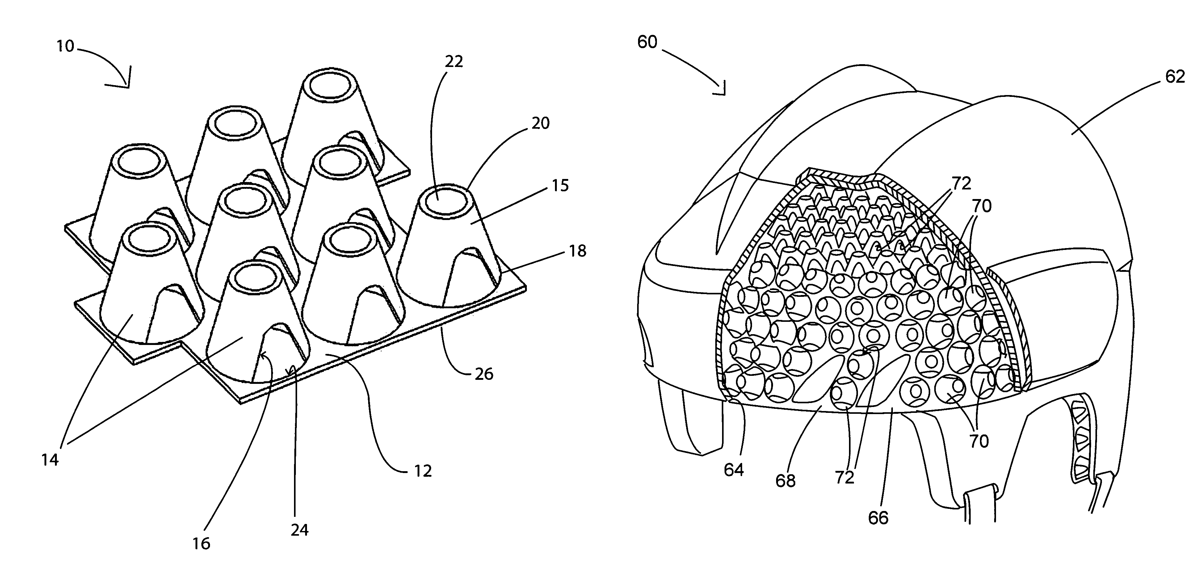
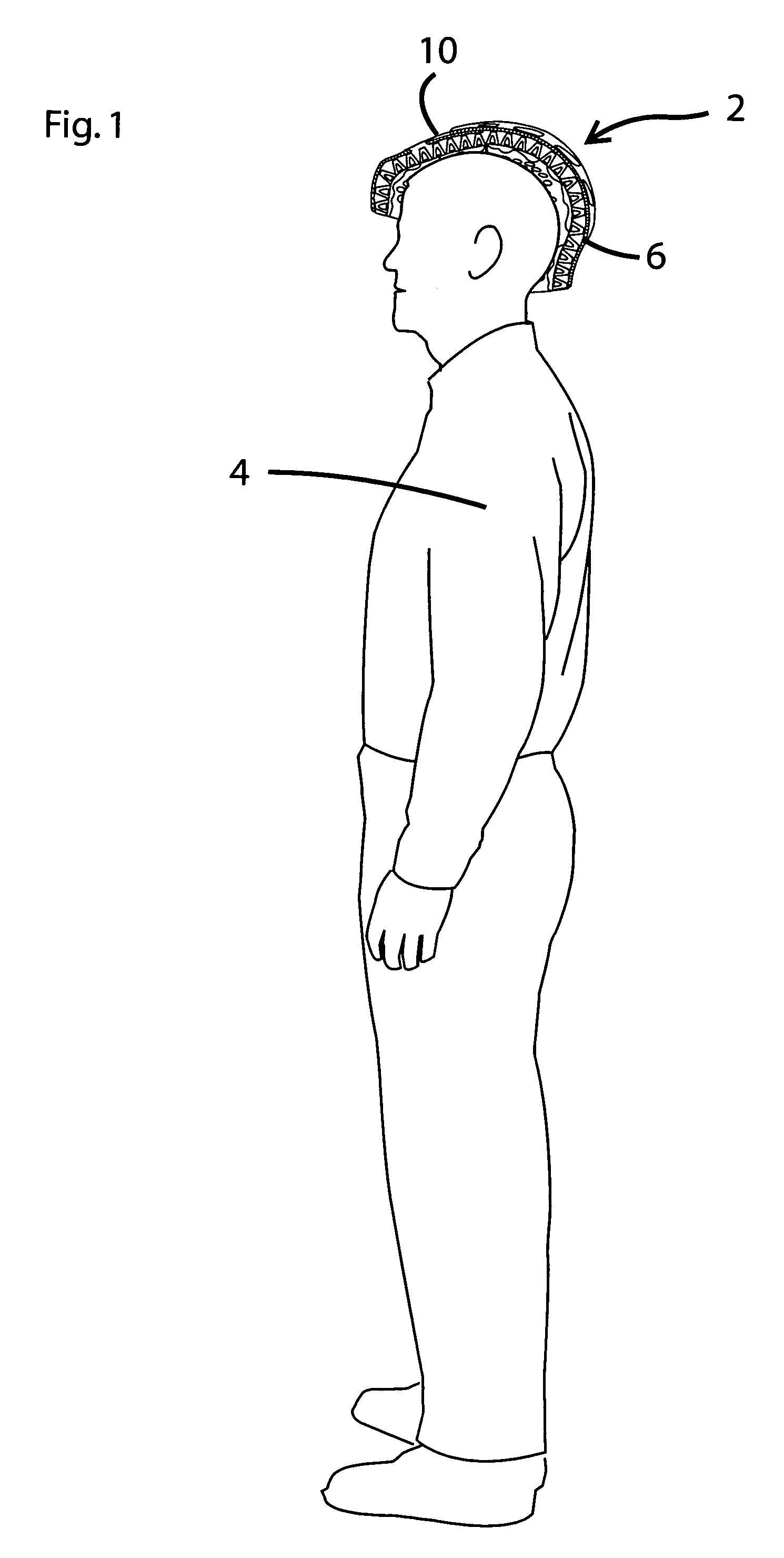
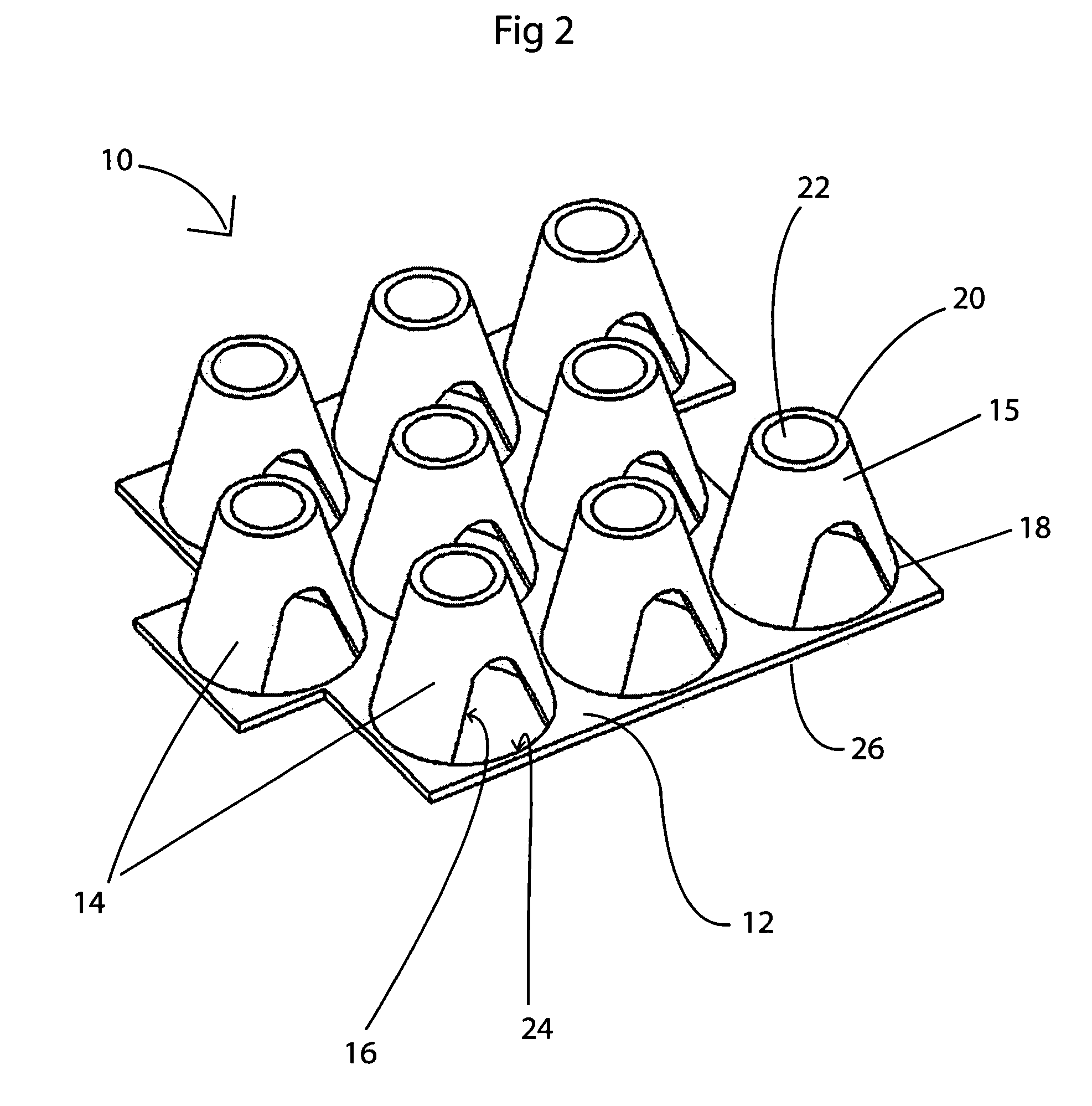
There is provided a shock absorbing structure comprising a generally planar surface made of a flexible plastic material. A plurality of upstanding, hollow support members extends from the planar surface. The support members are made of flexible plastic material. There is also a plurality of openings in each of the support members, the openings define air passages within the shock absorbing structure to allow air to flow through the support members. The shock absorbing structure may be used in helmets, shin pads, kneepads, elbow pads, shoulder pads, chest protectors, gloves, pants and footwear.

Description

CROSS REFERENCE TO RELATED APPLICATIONS[0001]This is a standard utility application claiming priority from U.S. Provisional Application Ser. No. 60 / 616,386, filed Oct. 6, 2004, the entire specification of which is incorporated herein by reference.BACKGROUND OF THE INVENTION[0002]1. Technical Field[0003]The present invention relates to a shock absorbing structure. More particularly, the present invention relates to a shock absorber having a plurality of upstanding, hollow support members made of flexible plastic material. Specifically, the invention relates to a shock absorbing structure that assists in allowing air flow around the structure.[0004]2. Background Information[0005]Helmets and other protective equipment typically use foam for impact absorption, specifically, expanded polystyrene (EPS), polyethylene (EPP) or thermoplastic blown foam. These foams do not allow heat to dissipate from the head or body. Heat stress has become a major detriment to exercise performance in athlet...

Claims


Application Information

Patent Timeline
Patent Type & Authority Patents(United States)
IPC IPC(8): A63B71/10
CPCA41D31/005A42B3/124A42B3/28A43B13/181F16F9/0481A63B71/10A41D31/285
Inventor COPELAND, STEVEWECKMAN, ROBERT L.LEE, HYO-CHUL
Owner PARADOX DESIGN SERVICES
Why Eureka
Try Eureka