Inflation valve with pneumatic assist

a technology of inflation valve and pneumatic assist, which is applied in the direction of liquid transfer device, application, liquid handling, etc., can solve the problems of avoiding the need for extensive machining of metal parts and the attendant manufacturing and assembly costs

Active Publication Date: 2010-03-09
HALKEY ROBERTS CORP
View PDF7 Cites 8 Cited by
  • Summary
  • Abstract
  • Description
  • Claims
  • Application Information

AI Technical Summary

Benefits of technology

[0013]For the purpose of summarizing this invention, this invention comprises a pneumatically assisted inflator for gas cylinders. The inflator of the invention uniquely comprises an inline configuration such that gas contained within the gas cylinder flows axially through the inflator to be exhausted therefrom and inflate the inflatable article. The inline configuration of the inflator of this invention reduces the stress otherwise imparted to the component parts thereof, and thereby allows most of the component parts to be manufactured from an injection molded high-strength plastic or the like.
[0014]Moreover, the inline configuration of the present invention eliminates the need for the O-ring seal of the inflator piston to wipe across the exhaust opening possibly bursting the O-ring through the exhaust opening. Further, possible damage to the O-ring by the edge of the exhaust hole as it is explosively wiped thereacross is eliminated.

Problems solved by technology

However, there presently exists a need for pneumatically assisted inflators that are configured in such a manner that virtually all of the components thereof may be manufactured from a high-strength, injectable plastic thereby obviating the need for extensive machining of metal parts and the attendant manufacturing and assembly costs thereof.

Method used


Image

  • Inflation valve with pneumatic assist
  • Inflation valve with pneumatic assist
  • Inflation valve with pneumatic assist

Examples


Embodiment Construction

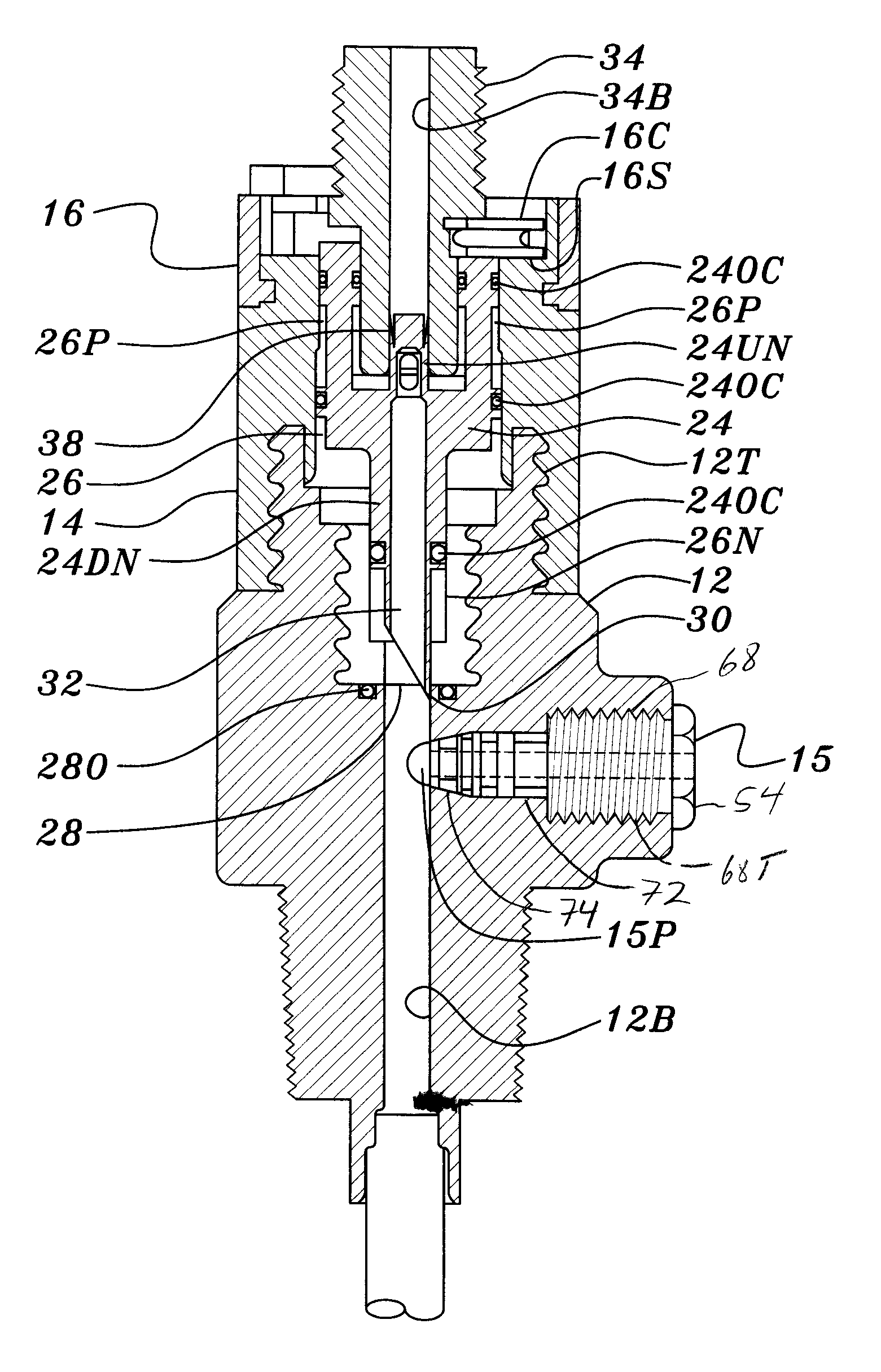
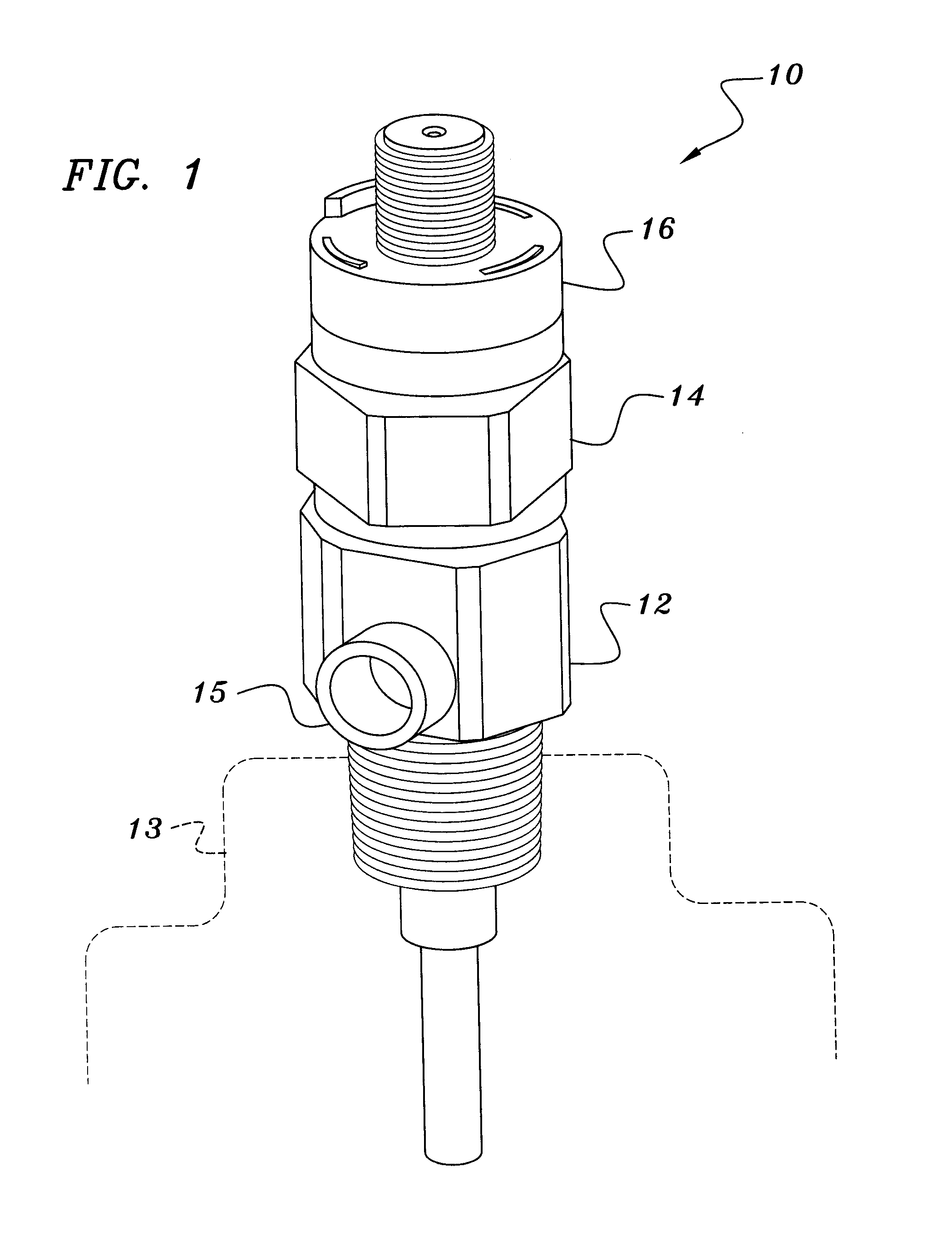
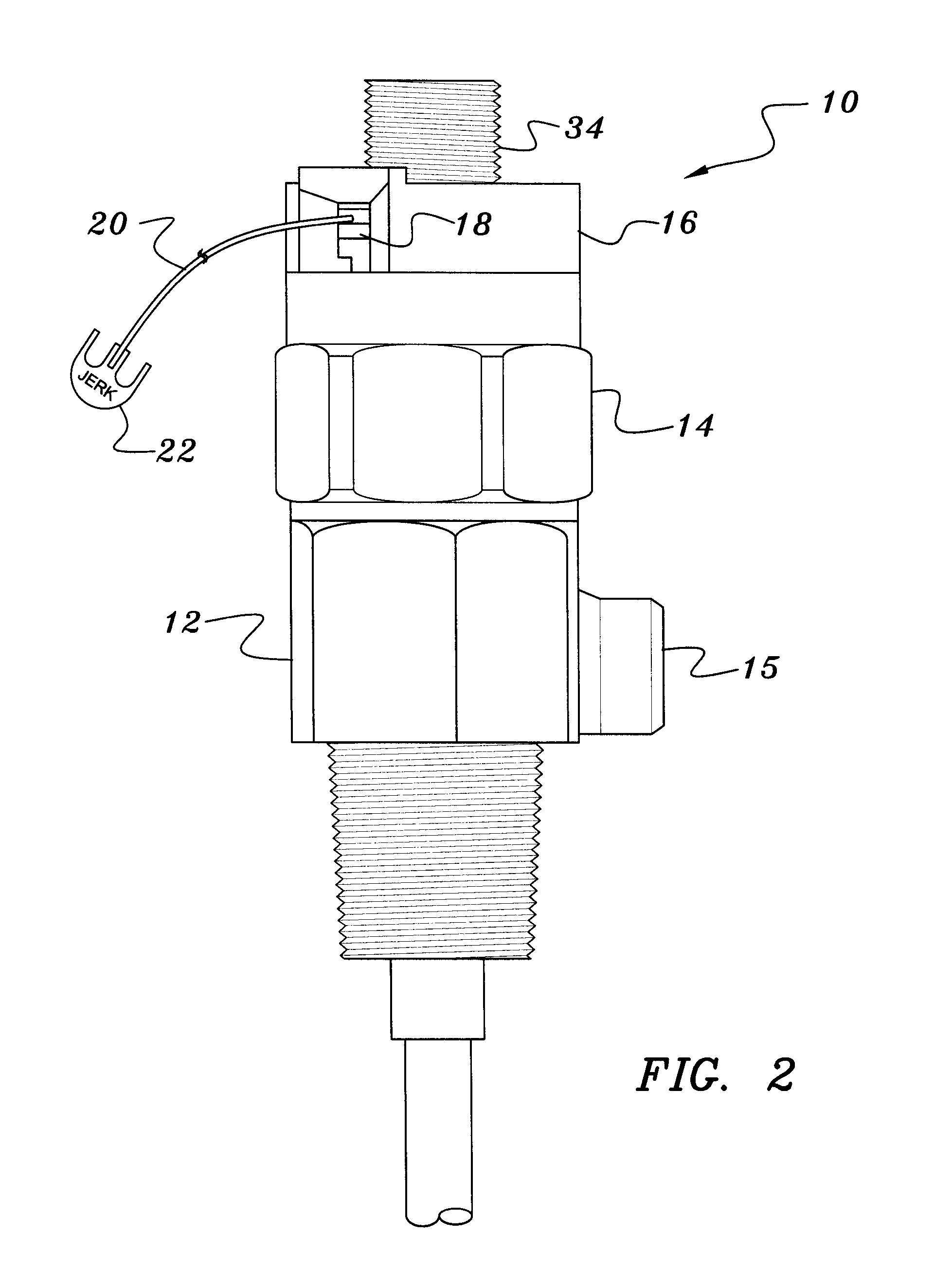
[0026]Referring to FIGS. 1 and 2, the inflator 10 of the invention comprises a valve portion 12 to which is threadably coupled an inflator portion 14. As will become evident hereinafter, the valve portion 12 may be threadably coupled to the threaded neck of a gas cylinder 13 (shown in phantom) to then be filled via inlet 15 without necessarily requiring the installation of the inflator portion 14. Then, after the gas cylinder 13 has been filled with the appropriate gas, the inflator portion 14 may be installed by simple threaded engagement with the valve portion 12.

[0027]The inflator portion 14 comprises a rotatable inflator collar 16 having a side opening 18 through which is threaded a lanyard cord 20 of a conventional jerk-to-inflate handle 22. The end of the lanyard cord 20 is connected to a rotatable cam 16C positioned inside the collar 16. The underside of the rotatable cam 16C including a cam surface 16S.

[0028]As shown in FIGS. 3 and 4, the inflator portion 14 further comprise...


PUM


Abstract

A pneumatically assisted inflator for gas cylinders comprises an inline configuration such that gas contained within the gas cylinder flows axially through the inflator to be exhausted therefrom and inflate an inflatable article. The inline configuration of the inflator reduces the stress otherwise imparted to the component parts thereof and thereby allows most of the component parts to be manufactured from an injection molded high-strength plastic or the like. The inflator comprises an inflator piston positioned within a piston cylinder that moves against a rotatable cam surface, such as a rotatable collar connected to a pull lanyard, to force a pierce pin to make at least a small pin hole in a frangible seal and allow high pressure gas from the gas cylinder to flow into the piston cylinder, whereupon the high pressure gas in the piston cylinder further moves the inflator piston to more fully force the pierce pin into the frangible seal to fully open the frangible seal.

Description

CROSS-REFERENCE TO RELATED APPLICATIONS[0001]This application is a continuation-in-part application of Ser. No. 10 / 935,944 filed Sep. 8, 2004, now U.S. Pat. No. 7,178,547 issued Feb. 20, 2007, which claims priority of provisional application No. 60 / 501,297, filed Sep. 8, 2003, the disclosures of which are each hereby incorporated by reference herein.BACKGROUND OF THE INVENTION[0002]1. Field of the Invention[0003]This invention relates to inflation valves for compressed gas cylinders used for inflating inflatable articles such as life rafts. More particularly, this invention relates to inflation valves that utilize the pressure of the gas in the gas cylinder to assist in the opening of the valve to a fully-open position by pulling on an inflation handle.[0004]2. Description of the Background Art[0005]Presently, there exists many types of inflation valves designed to be used in conjunction with compressed gas cylinders or the like. In their simplest forms, inflation valves may compris...

Claims


Application Information

Patent Timeline
Patent Type & Authority Patents(United States)
IPC IPC(8): B67B7/64F16K17/14B67D99/00F16K17/40
CPCB63C9/24F16K15/20Y10T137/1767
Inventor MACKAL, GLENN H.
Owner HALKEY ROBERTS CORP
Why Eureka
Try Eureka