Method and device for 3D reconstruction of the distribution of fluorescent elements

a fluorescent element and 3d reconstruction technology, applied in the field of fluorescence molecular imaging, can solve the problems of difficult in vivo measurement, high cost of calculation time, and complex reconstruction techniques

Active Publication Date: 2010-03-09
COMMISSARIAT A LENERGIE ATOMIQUE ET AUX ENERGIES ALTERNATIVES
View PDF6 Cites 14 Cited by
  • Summary
  • Abstract
  • Description
  • Claims
  • Application Information

AI Technical Summary

Benefits of technology

[0018]The detection of the signal(s) is preferably performed in a measurement window making it possible to recover almost all of the photons emitted by the fluorescence. The calculation of the values of a variable independent of the lifetime can therefore be done by taking into account the entirety of the signal(s) detected in this measurement window.
[0021]This method can be adapted to transformations other than the mean time (for example, the Mellin-Laplace transforms), which make it possible to do without the lifetime owing to the normalisation.
[0024]The determination of the position or the spatial distribution of fluorophores in the medium can be achieved by a method of reversal using values of the variable. The reversal method can result from the minimisation of an error function between the measurement and said variable, for example using a simplex method.
[0040]According to an embodiment, the means for determining the position or the spatial distribution of fluorophores in the medium implement a minimisation of an error function of the values of said variable, which minimisation can be a processing operation by adjustment using a simplex method.

Problems solved by technology

The time data is the data that contains the most data content on the traversed tissue, but for which the reconstruction techniques are the most complex.
However, this lifetime can be sensitive to the environment and is difficult to measure in vivo.
A poor choice of this parameter leads to erroneous results.
This method is more complex and costly in calculation time because it is based on numerical calculations to obtain the Laplace transforms (the analytical expression is not easy to find).
Therefore, there is the problem of determining the spatial distribution of fluorophores in a diffusing medium, without prior knowledge of the fluorescence lifetime.

Method used


Image

  • Method and device for 3D reconstruction of the distribution of fluorescent elements
  • Method and device for 3D reconstruction of the distribution of fluorescent elements
  • Method and device for 3D reconstruction of the distribution of fluorescent elements

Examples


Embodiment Construction

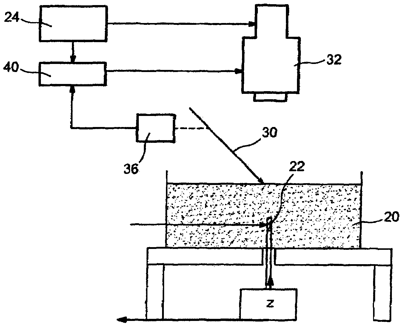
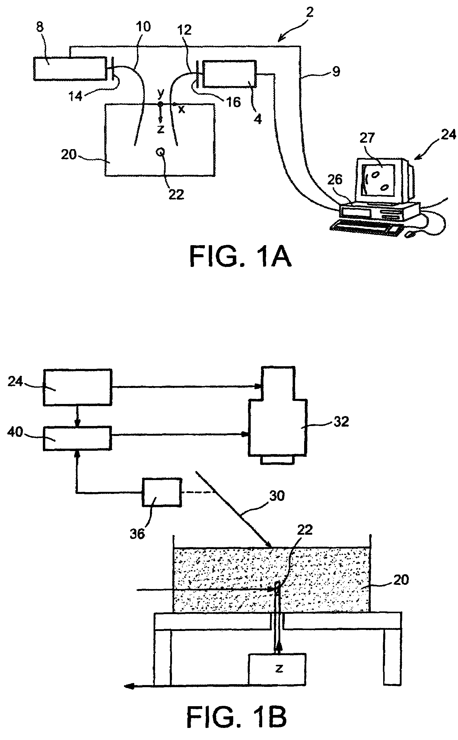
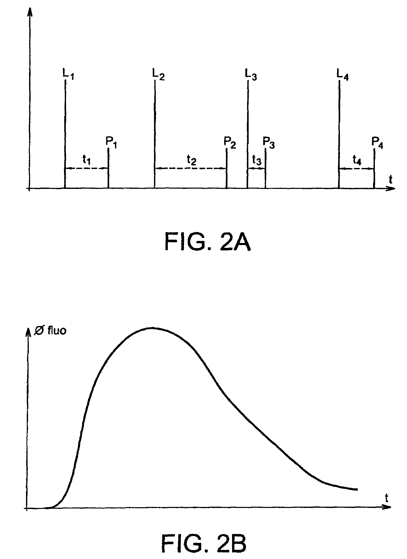
[0013]The invention first relates to a method for processing emitted fluorescence signals, after excitation by radiation from a radiation source, by at least one fluorophore with a lifetime τ in a surrounding medium, which signals are detected by detection means, and which method comprises:[0014]the detection of a plurality of fluorescence signals (Φfluo) emitted by the fluorophore(s) in the surrounding medium, each signal corresponding to a relative position, on the one hand of the fluorophore(s) and on the other hand of the source and the detection means,[0015]the calculation, based on these detected fluorescence signals, of values of a variable, independent of τ but dependent on the position or the spatial distribution of fluorophores in said medium,[0016]the determination of the position or the spatial distribution of fluorophores in said medium on the basis of the values of said variable.

[0017]The fluorophore(s) can be bonded to biological tissue, for example target cells of in...


PUM

PropertyMeasurementUnit
distanceaaaaaaaaaa
wavelengthaaaaaaaaaa
heightaaaaaaaaaa

Abstract

A device and method for processing fluorescence signals emitted after excitation by radiation coming from a radiation source, by at least one fluorophore with a lifetime τ in a surrounding medium, which signals are detected by detection means, and which method includes the calculation, on the basis of detected fluorescence signals, of values of a variable, independent of τ, of the position or the distribution of fluorophore in said medium.

Description

CROSS-REFERENCE TO RELATED PATENT APPLICATION OR PRIORITY CLAIM[0001]This application claims the benefit of a French Patent Application No. 06-07065, filed on Aug. 2, 2006, in the French Intellectual Property Office, the disclosure of which is incorporated herein in its entirety by reference.TECHNICAL FIELD AND PRIOR ART[0002]This invention relates to the field of fluorescence molecular imaging on biological tissue by time-resolved optical methods.[0003]It applies in particular to optical molecular imaging on small animals and optical molecular imaging on humans (brain, breast, and other organs where fluorophores can be injected).[0004]The optical fluorescence molecular imaging optical techniques are now being increasingly developed owing to the use of specific fluorescent markers. These bind preferentially to the target cells of interest (for example cancer cells) and provided better detection contrast than non-specific markers. These techniques are designed to spatially locate the...

Claims


Application Information

Patent Timeline
Patent Type & Authority Patents(United States)
IPC IPC(8): G01N21/64
CPCG01N21/6408G01N21/6428G01N21/6456A61B5/0059
Inventor LAIDEVANT, AURELIEDA SILVA, ANABELADINTEN, JEAN-MARC
Owner COMMISSARIAT A LENERGIE ATOMIQUE ET AUX ENERGIES ALTERNATIVES
Why Eureka
Try Eureka