Deployment of seismic sensor

a technology for seismic sensors and deployment plans, applied in the direction of measuring devices, scientific instruments, instruments, etc., can solve the problems of difficult to evaluate uneven seabeds, less effective, and seabeds may have become soft, so as to reduce the disadvantages of known equipment and methods, easy to use, and accurate

Active Publication Date: 2010-03-09
SEABED GEOSOLUTIONS
View PDF28 Cites 29 Cited by
  • Summary
  • Abstract
  • Description
  • Claims
  • Application Information

AI Technical Summary

Benefits of technology

[0011]The main object of the invention is to provide an arrangement for the deployment of sensor nodes, which substantially reduces the disadvantages of known equipment and methods. More specifically, it is an object to provide such an arrangement, which can deploy sensor nodes in an easy, accurate, repeatable, and damage-free manner. By the word “accurate” it is meant both the position on the seabed, and the insertion into the seabed, particularly with regard to the vertical orientation.
[0012]Another object is to provide an arrangement which is easy to use and which can reduce expenses compared to the use of an ROV, which is also effective in poor visibility.
[0013]With such an arrangement, one can deploy sensor nodes in a satisfactory manner, without the use of an ROV, or by using a simple ROV as surveillance equipment. This reduces wearing and damage risk both on the deployed equipment, and on the deployment equipment. In addition, the invention makes it possible to perform a quicker deployment than is possible with known equipment. The deployment can take place with satisfactory positional accuracy, even at zero visibility, and with an inclined seabed.

Problems solved by technology

This may function well in shallow waters, but becomes less effective with poor visibility and a soft seabed.
At zero visibility, it is difficult to evaluate an uneven seabed, and how deep a sensor node has been inserted.
Furthermore, the seabed may have become softer due to whirling of the bottom, something which can affect the positioning accuracy, and the quality of the mechanical connection between the sensor node and the seabed.
It is undesirable if the sensor node cannot be deployed with a defined orientation of the main axis, which is vertical in practice.
Influence from currents, for instance due to river mouths, strong wave motions, bad weather, and an inclined seabed, may cause the inaccuracy to increase.
The use of an ROV will generally involve risk of damage, which will increase in poor deployment conditions.
Depending on the sea conditions, such use of an ROV may result in severe damage to the sensor arrangement.
This embodiment is burdened with the same drawbacks as mentioned above, with regard to the deployment of the sensor nodes on the seabed, under poor visibility and soft seabed.
This equipment is complex, difficult to operate, and burdened with the problems related to the deployment by means of an ROV or ROT.
Furthermore, the usefulness of the method will be limited by the shearing strength, density, and the sedimentary characteristics of the seabed in question.

Method used


Image

  • Deployment of seismic sensor
  • Deployment of seismic sensor
  • Deployment of seismic sensor

Examples


Embodiment Construction

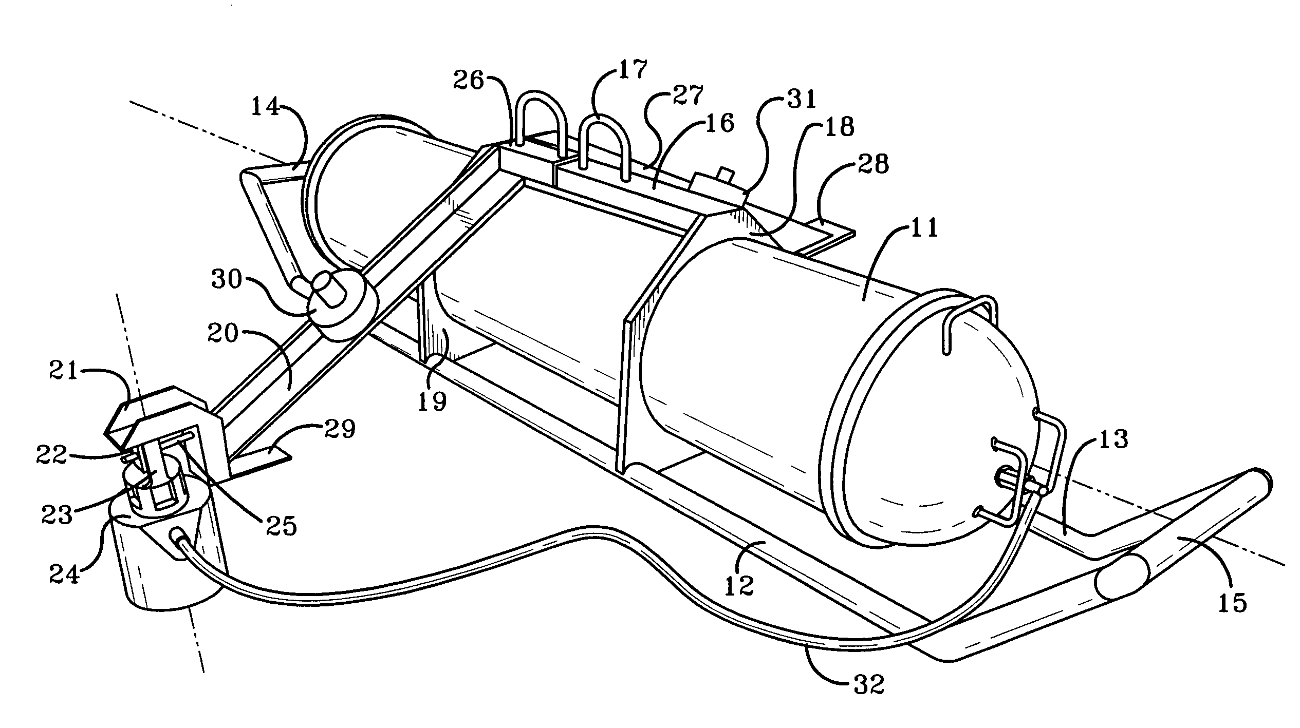
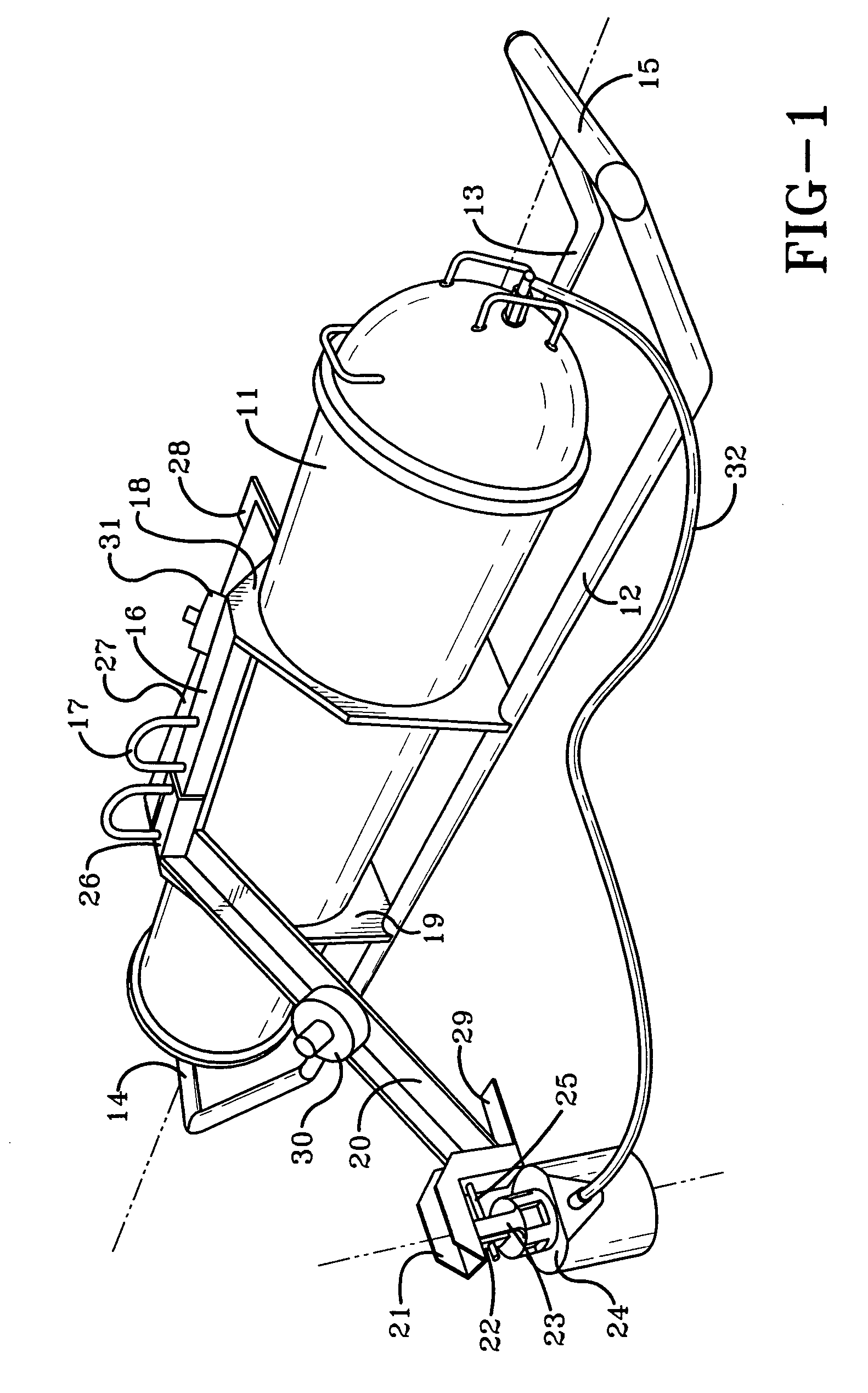
[0018]FIG. 1 illustrates a cylindrical container 11, having a longitudinal main axis, that contains registering and reporting equipment and a power supply for the operation of a submerged sensor node. The container 11 is supported by two parallel skids 12, 13, which are made of a pipe material and which have upwardly bent ends 14, 15, that are connected to each other. A yoke 16, having a lifting bow 17, is coupled to the top side of the container 11. The yoke 16 is coupled to the container 11 with rings 18, 19, which encircle the container 11 at each end of the yoke.

[0019]On one side of this structure, a carrier arm 20 extends outwardly. The carrier arm 20 has an inner end that is removably attached to the yoke 16 and an outer end that carries an outwardly extending bracket 21. At its underside, the bracket 21 has a downwardly extending releasable fastener 22 for coupling to a carrier bracket 23 located on the top of a sensor node 24. The carrier bracket 23 can be arranged for gripp...


PUM


Abstract

An arrangement for the deployment of seismic sensor units, such as sensor nodes (24), on the seabed includes a frame structure that is adapted to carry a container (11) for containment of a data registration unit and additional auxiliary equipment for the sensor node. The arrangement has supports (12, 13) that can rest against the seabed, and an attachment means (17) for a lifting hook, for raising and lowering by means of a crane. There is a holder (20) for the sensor node (24) that can be positioned on the seabed and which is connected to the container through a signal cable (32). A releasable attachment means (22) holds the sensor node (24) in a downwardly extending position with respect to the supports (12, 13). The attachment means (22) is located with a horizontal distance from the container (11). A latch mechanism (25) for the attachment means (22) is adapted to release the sensor node (24).

Description

[0001]This application claims priority from Norwegian Patent Application no. 20041900, filed May 7, 2004 which is incorporated herein by reference.I. BACKGROUND OF THE INVENTION[0002]A. Field of Invention[0003]This invention relates to an arrangement for the deployment of seismic sensor units on the seabed.[0004]B. Description of the Related Art[0005]To perform seismic explorations in formations under the sea, a plurality of seismic nodes are arranged on the seabed, preferably in an orderly manner. These sensor nodes must be in contact with a solid medium, leading to requirements for the deployment operation. One such arrangement is provided in commonly owned Norwegian Patent Application no. 20025896 and corresponding U.S. Pat. No. 7,324,406 which are hereby incorporated by reference. With this arrangement a remotely operated registration and reporting unit is connected to each sensor node, for telemetric transmission of data to a control center located in an above-water receiver. I...

Claims


Application Information

Patent Timeline
Patent Type & Authority Patents(United States)
IPC IPC(8): G01V1/38G01V1/16
CPCG01V1/3852G01V1/16
Inventor BERG, EIVINDNAS, JOHAN FREDRIKPERSSON, THORESTORESUND, SVEN MAGNC
Owner SEABED GEOSOLUTIONS
Why Eureka
Try Eureka