Transversely isotropic model for wellbore stability analysis in laminated formations

a technology of laminated formations and stability analysis, applied in the field of model of predicting wellbore stability in laminated formations, can solve problems such as economic losses, wellbore instability, and common stress-induced wellbore failures

Active Publication Date: 2010-03-09
SCHLUMBERGER TECH CORP
View PDF4 Cites 7 Cited by
  • Summary
  • Abstract
  • Description
  • Claims
  • Application Information

AI Technical Summary

Problems solved by technology

Stress-induced wellbore failures are common in oilfield exploration and production.
This problem has been an important concern for operators, as borehole collapses and lost circulation during well drilling can cause economic losses.
Such stress-induced wellbore failures can also cause problems in production operations, as sanding control and management are of utmost importance for the economy of a field.
However, in most cases anisotropy behavior of formation is found, and wellbore failures related to bedding or laminated formations have been widely recognized as a common cause of wellbore instability.
Thus it is difficult to apply the theory based on the assumption that formation rock is a continuous isotropic medium on the actual analysis of laminated formations.
Unfortunately, due to the mathematical difficulty, there is no unique analytical solution to the problem of a borehole embedded in a transversely isotropic material.
However, Aadnoy's model has disadvantage that it simplified the transversely isotropic model by using only three elastic parameters, rather than the five that are actually required.
Willson et al. also adopted the single plane failure model in analyzing the wellbore stability problems in bedding formations, but unrealistically assumed isotropic elastic behavior when computing the deformation and induced stresses in their model.
However, these numerical methods have not been applied to field applications systemically.
First, in laminated formations, boundaries or interfaces between different formations pose great difficulties in discretization of the elements, especially in the cases when the borehole axis is inclined to the axis of the laminated formation plane.
Second, 3-D FEM is a computational time costly approach and it is impossible to use this method in a log-based analysis.

Method used


Image

  • Transversely isotropic model for wellbore stability analysis in laminated formations
  • Transversely isotropic model for wellbore stability analysis in laminated formations
  • Transversely isotropic model for wellbore stability analysis in laminated formations

Examples


Embodiment Construction

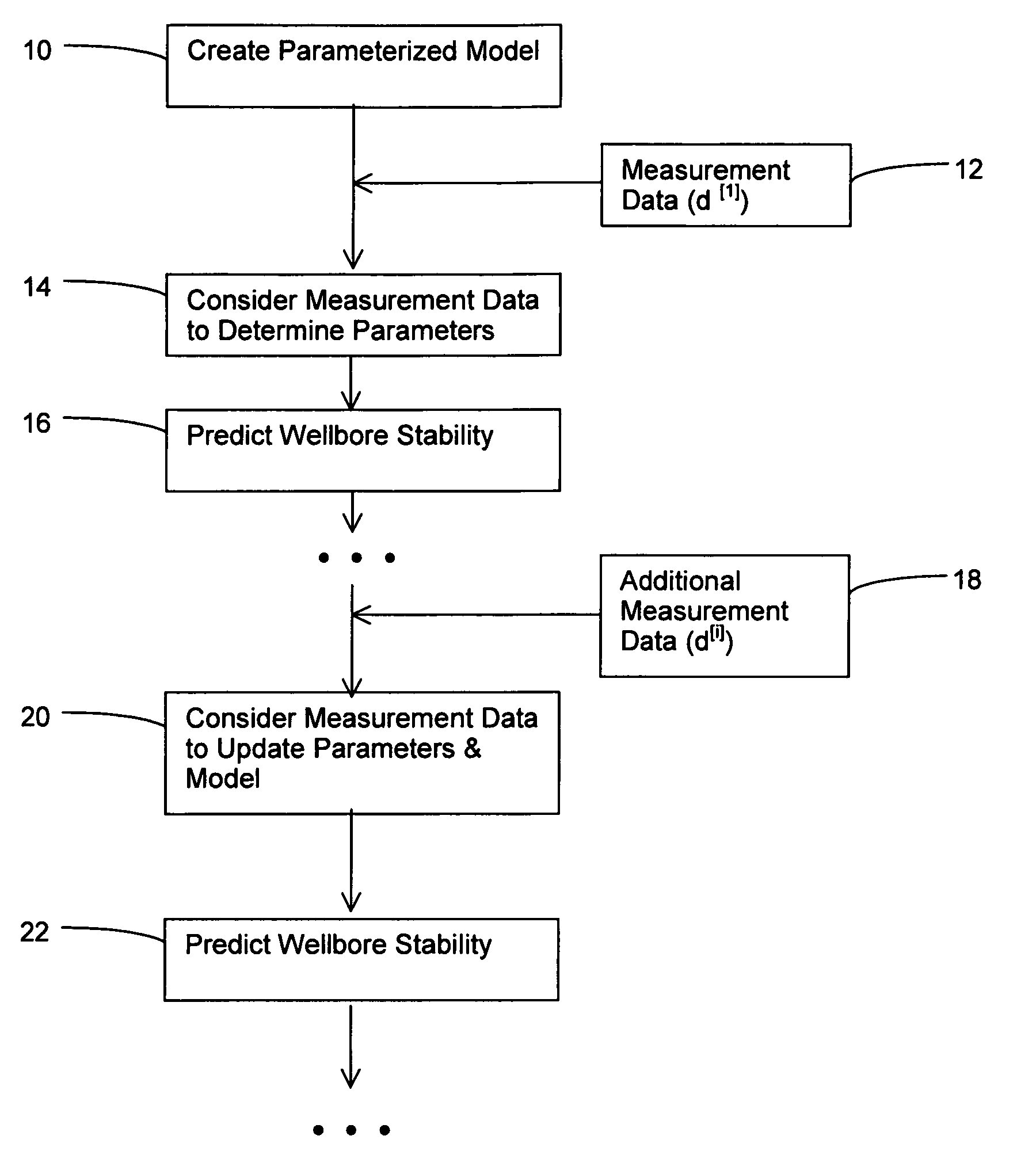
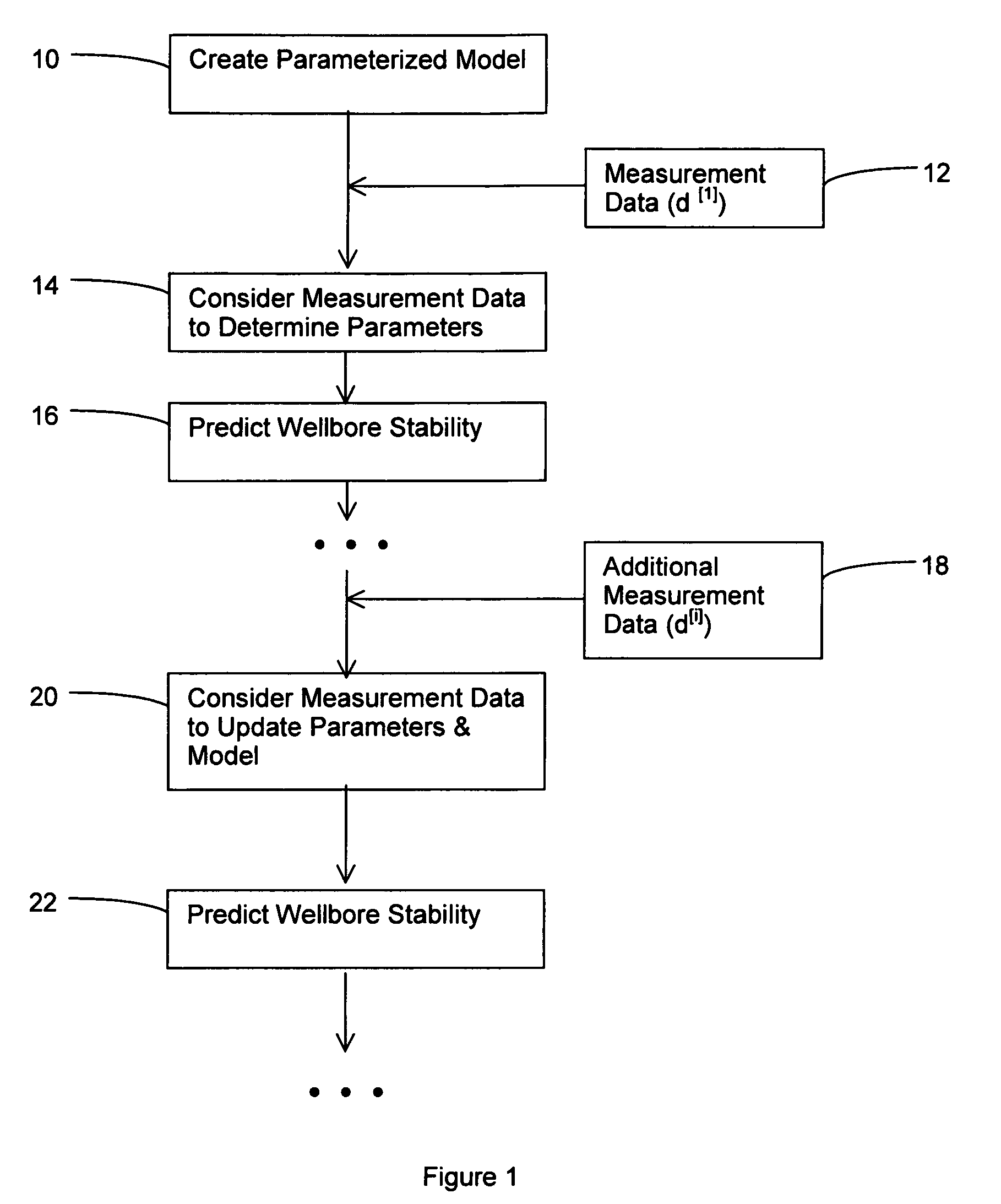
[0027]FIG. 1 shows several steps associated with the present method, apparatus and article of manufacture and provides a general overview of the invention. In the Create Parameterized Model Step 10, a parameterized model of the wellbore in laminated formation is created. The parameterized model includes a plurality of laminated formation and wellbore related parameters. In one embodiment of the invention, the laminated formation and wellbore related parameters include 5 elastic parameters of laminated formation, e.g. E, E′, υ, υ′ and G′. Respectively, E and E′ are the Young's modulus with respect to directions lying in the plane of isotropy and perpendicular to it; υ is the Poisson coefficient characterizing the transverse reduction in the plane of isotropy for tension in the same plane; υ′ is the Poisson coefficient characterizing the transverse reduction in the plane of isotropy for tension in a direction normal to it; and G′ is the shear modulus for planes normal to the plane of ...


PUM


Abstract

A method of predicting wellbore stability is provided and includes: creating a parameterized model of a wellbore in laminated formation, the parameterized model including a plurality of laminated formation and wellbore related parameters; considering measurement data to determine the laminated formation and wellbore related parameters; updating the parameterized model by adopting the determined laminated formation and wellbore related parameters; and applying the updated parameterized model to derive a solution of wellbore stability.

Description

FIELD OF THE INVENTION[0001]The present invention relates generally to oil and gas well drilling and hydrocarbon production. More particularly, the present invention relates to a model of predicting wellbore stability in laminated formations.BACKGROUND OF THE INVENTION[0002]Stress-induced wellbore failures are common in oilfield exploration and production. This problem has been an important concern for operators, as borehole collapses and lost circulation during well drilling can cause economic losses. Such stress-induced wellbore failures can also cause problems in production operations, as sanding control and management are of utmost importance for the economy of a field. Therefore, to safely drill a deep well for hydrocarbon exploration or production, it is necessary to predict the wellbore stability and avoid wellbore failures, and a better understanding of the rock mechanical properties and failure behavior is essential to improve the economics of an oilfield development.[0003]...

Claims


Application Information

Patent Timeline
Patent Type & Authority Patents(United States)
IPC IPC(8): G06F7/48G06F17/10
CPCE21B47/026G01V1/40
Inventor BRADFORD, IANYAN, GONGRUIATKINSON, COLIN
Owner SCHLUMBERGER TECH CORP
Why Eureka
Try Eureka