Sheet conveying device and image forming apparatus

a conveying device and a technology for forming apparatus, applied in the direction of registering devices, thin material processing, article separation, etc., can solve the problems of unbalanced shifting force, sheet to be oblique, unbalanced lateral shifting force, etc., and achieve high precision

Inactive Publication Date: 2010-03-16
CANON KK
View PDF7 Cites 15 Cited by
  • Summary
  • Abstract
  • Description
  • Claims
  • Application Information

AI Technical Summary

Benefits of technology

[0015]The present invention provides a sheet conveying device and an image forming apparatus that can correct a displacement with high precision even when the displacement of the sheet in the width direction is large.
[0016]According to an aspect of the present invention, a sheet conveying device for conveying a sheet includes a displacement-amount detector and a plurality of sheet conveying roller portions. The displacement-amount detector is configured to detect an amount of displacement of a conveyed sheet from a conveyance reference in a width direction being substantially perpendicular to a sheet conveying direction. The plurality of sheet conveying roller portions are configured to be shiftable in a direction substantially perpendicular to the sheet conveying direction while pinching the sheet having the amount of displacement detected by the displacement-amount detector. Before the sheet reaches the sheet conveying roller portions, the sheet conveying roller portions are shifted based on the amount of displacement detected by the displacement-amount detector from a conveyance-reference position in a direction in which the sheet is displaced. After the sheet reaches the sheet conveying roller portions, the sheet conveying roller portions are shifted while pinching the sheet so as to reduce the amount of displacement.

Problems solved by technology

In this case, the frictional force between the guiding surface of the conveying path and the large-size sheet Sa unbalances the shifting force.
In addition, the frictional force to the guiding surface of the conveying path may cause the sheet to be oblique.
In this case, because both the frictional forces to the guiding surface of the conveying path and the forces of pinching the sheet are different between the left and right conveying rollers 305, the lateral shifting force is unbalanced.
As a result, slippage occurs and the sheet Sb cannot be shifted by the accurate amount.

Method used


Image

  • Sheet conveying device and image forming apparatus
  • Sheet conveying device and image forming apparatus
  • Sheet conveying device and image forming apparatus

Examples


first embodiment

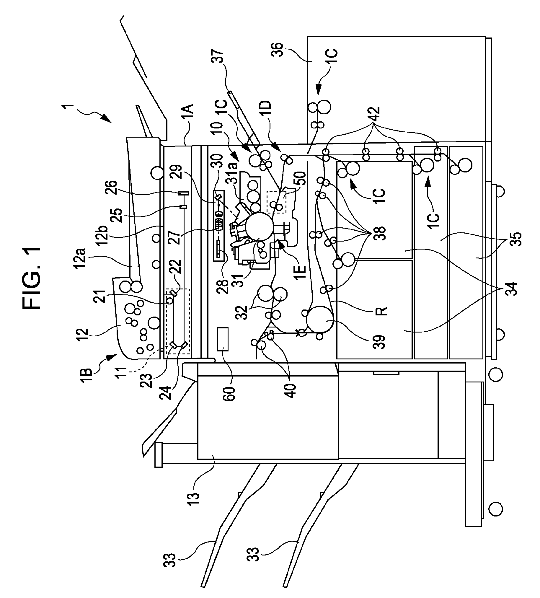
[0036]FIG. 1 illustrates a structure of a digital copier being one example of an image forming apparatus that has a sheet conveying device according to the present invention.

[0037]As illustrated in FIG. 1, a digital copier 1 includes a main body 1A thereof, an image reader device 1B configured to read a document image, and a sheet processing device 13 configured to process a sheet S ejected from the main body 1A. The image reading device 1B is disposed above the main body 1A. The sheet processing device 13 is disposed at a side of the main body 1A.

[0038]The image reading device 1B includes a platen glass 12b serving as an original plate, a scanner unit 11 configured to read a document image, and a document feeder 12 for feeding a document to the platen glass 12b.

[0039]The main body 1A includes an image forming unit 10 having a photosensitive drum 31, a sheet feeding unit 1C configured to feed a sheet supported on sheet cassettes 34 and 35, and a sheet conveying device 1D configured...

second embodiment

[0109]Such a mode, in which the HP of each of the pair of shift rollers 305 is changed according to the sheet size, will now be described as the present invention.

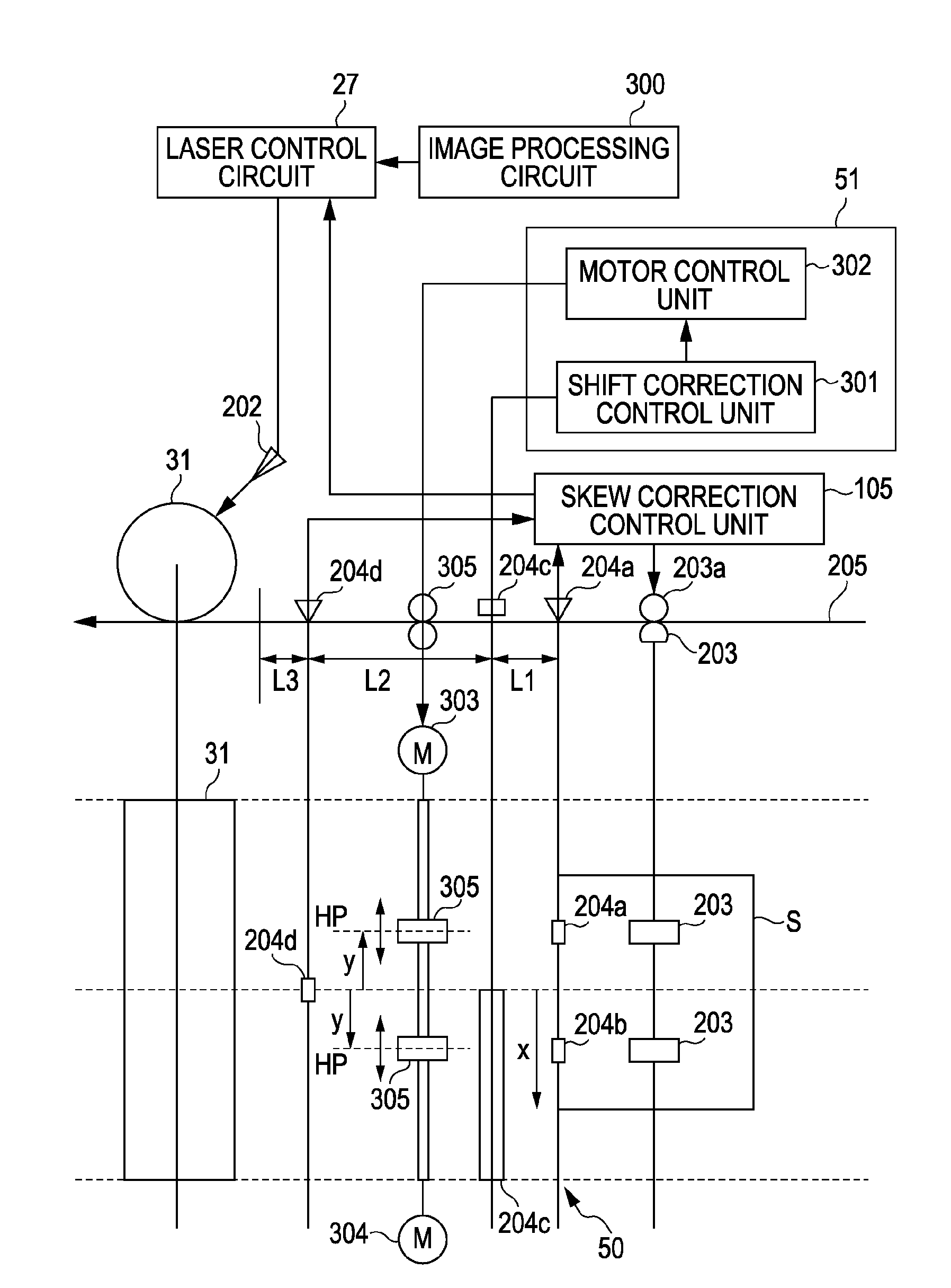
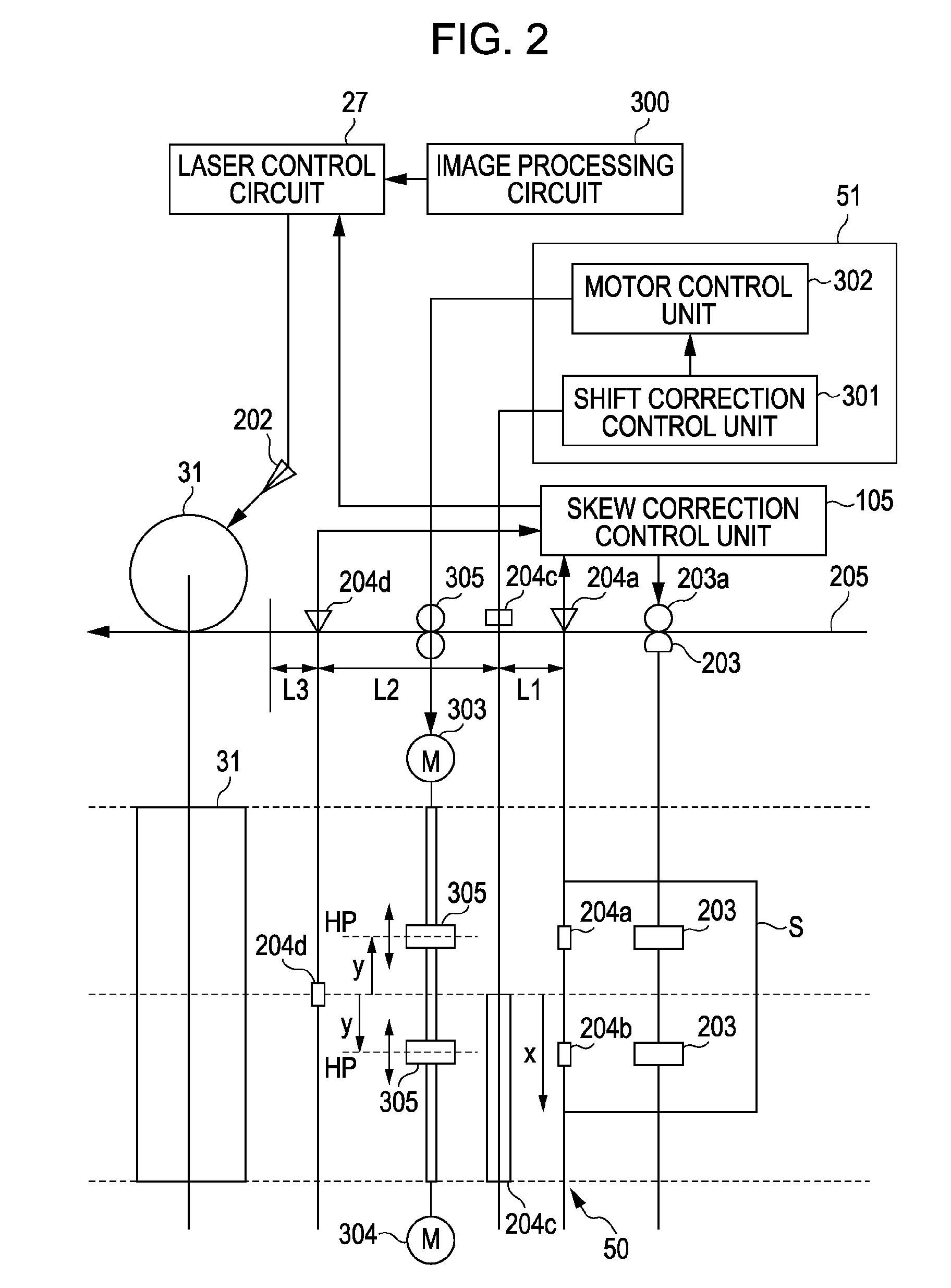
[0110]FIG. 13 illustrates a structure and a control block diagram of the sheet correcting unit 50 included in the sheet conveying device according to the present embodiment. In FIG. 13, the same reference numerals as in FIG. 2 indicate equivalent or corresponding parts.

[0111]In FIG. 13, an HP change motor 306 is a motor that changes the HP of each of the pair of shift rollers 305. The HP change motor 306 enables the distance y from the conveyance reference for each of the pair of shift rollers 305 to be changed according to the sheet size. That is, in the present embodiment, the HP change motor 306 being a gap changing portion enables the gap between the shift rollers in a direction substantially perpendicular to the sheet conveying direction to be changed according to the length of the sheet in the width direction.

[0112]I...


PUM

PropertyMeasurementUnit
lengthaaaaaaaaaa
lengthaaaaaaaaaa
CIS position displacement detectingaaaaaaaaaa

Abstract

A sheet conveying device for conveying a sheet includes a displacement-amount detector configured to detect an amount of displacement of a conveyed sheet from a conveyance reference in a width direction being substantially perpendicular to a sheet conveying direction and a plurality of sheet conveying roller portions configured to be shiftable in a direction substantially perpendicular to the sheet conveying direction while pinching the sheet having the amount of displacement detected by the displacement-amount detector. Before the sheet reaches the sheet conveying roller portions, the sheet conveying roller portions are shifted based on the amount of displacement detected by the displacement-amount detector from a conveyance-reference position in a direction in which the sheet is displaced. After the sheet reaches the sheet conveying roller portions, the sheet conveying roller portions are shifted while pinching the sheet so as to reduce the amount of displacement.

Description

BACKGROUND OF THE INVENTION[0001]1. Field of the Invention[0002]The present invention relates to a sheet conveying device and an image forming apparatus, and in particular, to a technique for correcting a positional displacement of a sheet in a width direction thereof.[0003]2. Description of the Related Art[0004]A typical image forming apparatus, such as a copier, printer, and a facsimile machine, has a sheet conveying device that conveys a sheet to an image forming portion for forming an image on the sheet.[0005]The sheet conveying device has a skew correcting portion to correct a skew of a sheet and conveys the sheet to the image forming portion. One example technique used in the skew correcting portion is to correct a skew by detecting the amount of skew of a sheet and changing the ratio between revolutions of a pair of conveying rollers arranged in a sheet width direction, to which a sheet conveying direction is perpendicular, or the number of revolutions of each of the conveyin...

Claims


Application Information

Patent Timeline
Patent Type & Authority Patents(United States)
IPC IPC(8): B65H7/02
CPCB65H9/002B65H2301/3613B65H2404/1424B65H2511/20B65H2511/222B65H2801/06B65H2220/01B65H2220/02
Inventor KINOSHITA, HIDEHIKOMORIYA, MASAAKIYAMAGUCHI, JUNNAKAGAWA, ATSUSHI
Owner CANON KK
Why Eureka
Try Eureka