Motorized collapsible step

a technology of movable steps and motors, which is applied in the direction of building scaffolds, transportation and packaging, building aids, etc., can solve the problems of giving the step a “spongy” or unstable feel, and achieve the effect of preventing excessive force from being transferred

Active Publication Date: 2010-03-16
LIPPERT COMPONENTS MFG INC
View PDF14 Cites 24 Cited by
  • Summary
  • Abstract
  • Description
  • Claims
  • Application Information

AI Technical Summary

Benefits of technology

[0008]Opposing ends of the pivot member are attached to a two-part linkage, each linkage mounted directly to the frame. The two-part linkage comprises a first link or crank mounted to rotate with the rod and pivotally attached to a second link. When the at least one step is in the extended position, the crank is substantially aligned and parallel with the straight link. In use, when the at least one step is in the extended position, the crank rotates around the pivot member, and engages against the frame to stop in a position in which the crank is nearly aligned with the link thereby preventing excessive forces from being transferred to the drive or transmission system when weight is placed on the step.
[0013]By utilizing the two-part linkage system on opposing ends of the pivot rod, the motor is nearly isolated from the forces exerted on the steps. This configuration improves the durability and longevity of motors for collapsible step assemblies while reducing servicing requirements, while also preventing the “spongy” or unstable feel conventional step assemblies can develop over time and avoiding “popping” type impacts that can occur if the step changes direction while being driven.

Problems solved by technology

However, these systems often fail over time, giving the step a “spongy” or unstable feel.

Method used


Image

  • Motorized collapsible step
  • Motorized collapsible step
  • Motorized collapsible step

Examples


Embodiment Construction

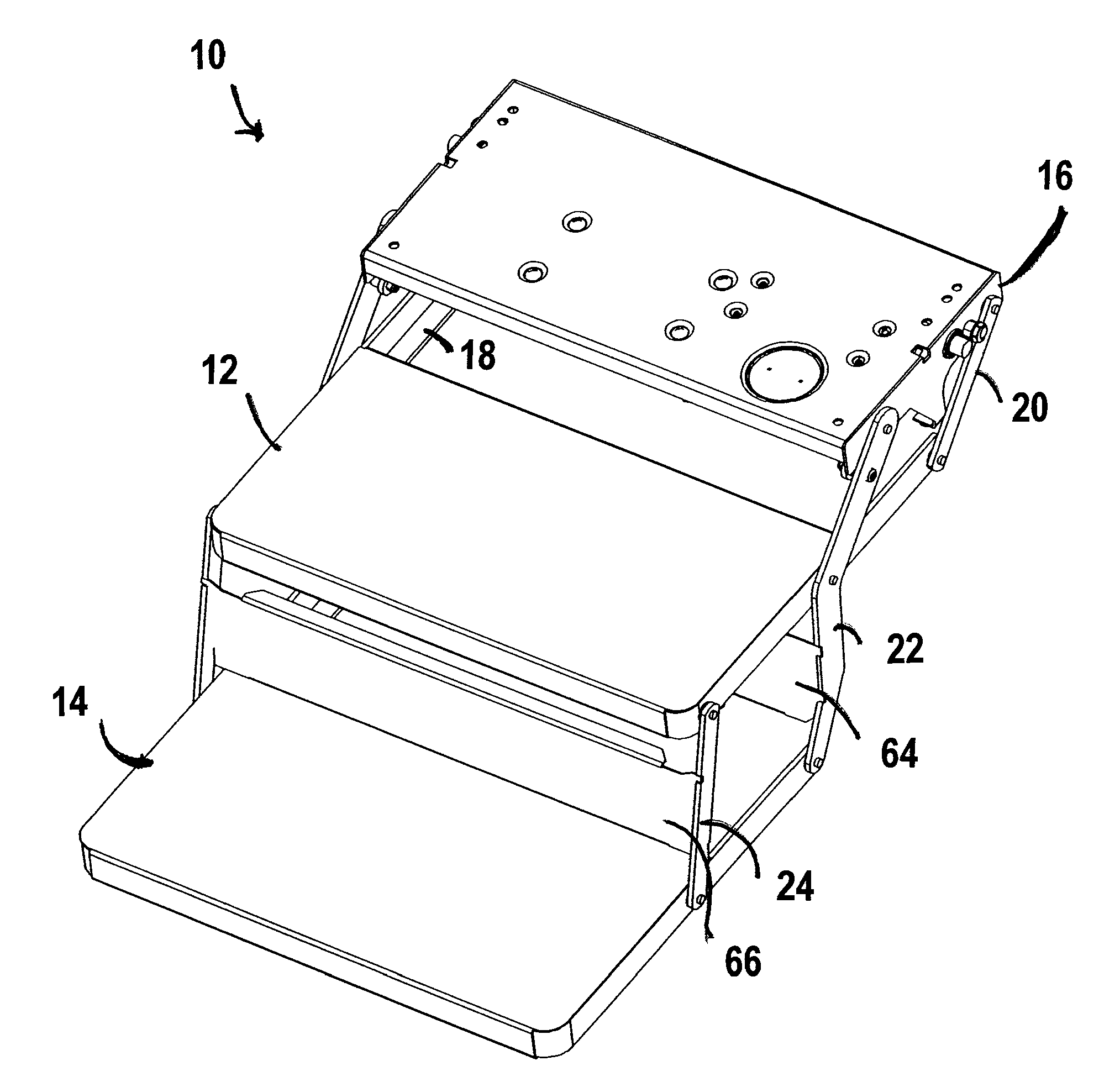
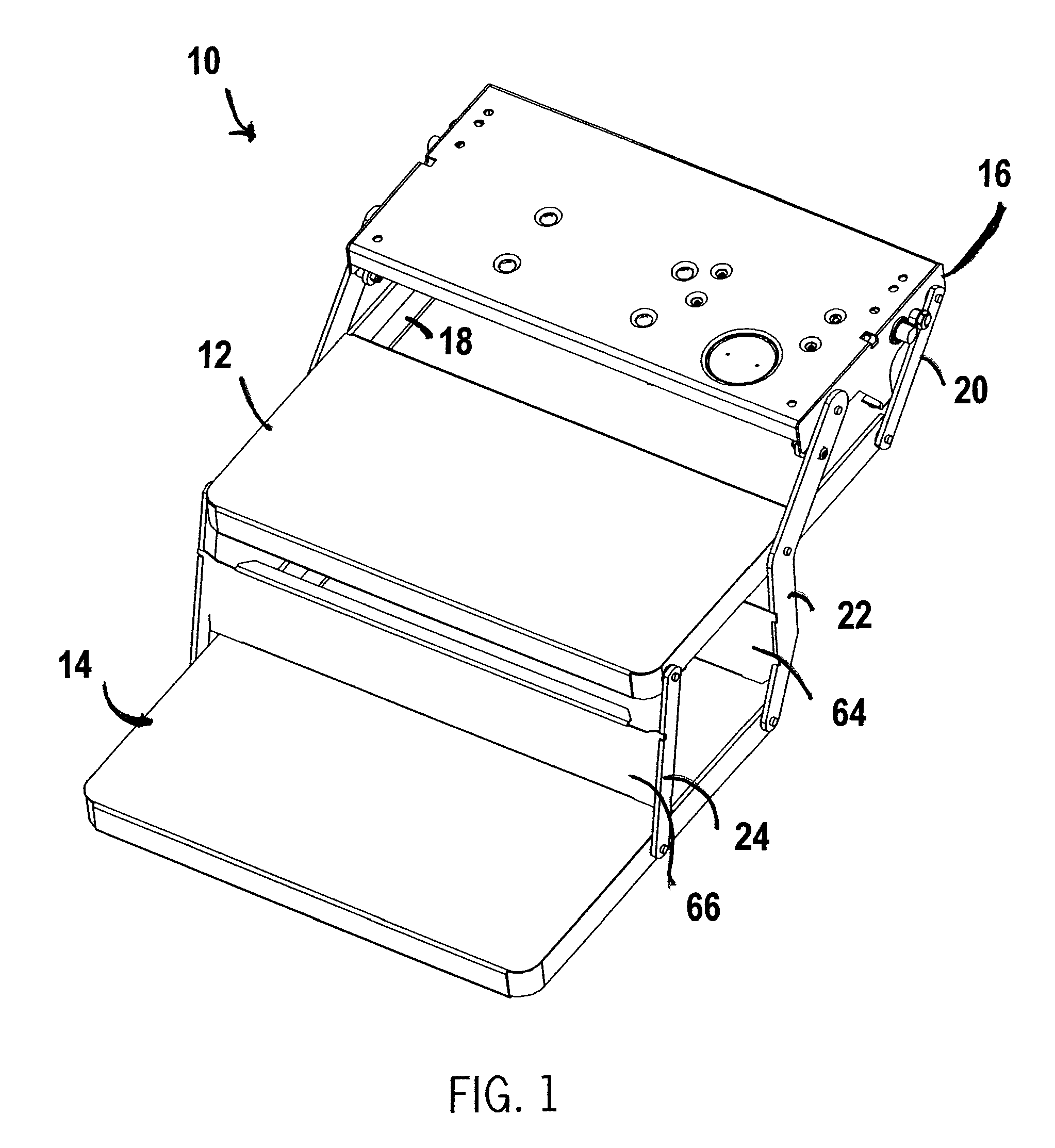
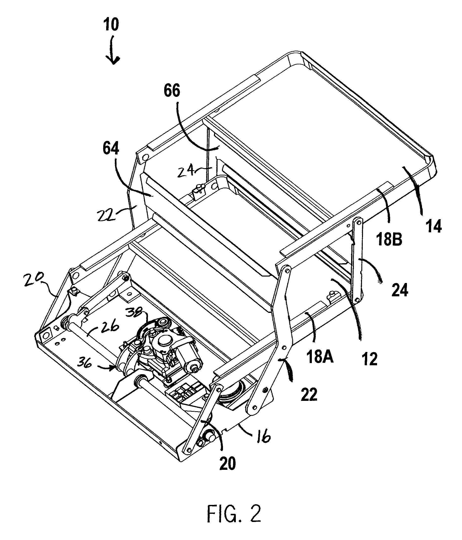
[0025]The invention comprises a collapsible step assembly 10 for use with recreational vehicles. Referring to FIGS. 1-4, the assembly 10 comprises a generally rectangular and planar upper step 12, a lower step 14 and a frame 16. The steps 12, 14 move between an extended position (FIGS. 1, 2 and 4) and a retracted position (FIG. 3), wherein the steps 12, 14 and frame 16 remain substantially parallel to one another at all times.

[0026]Each step 12, 14 may be covered with a non-skid material (not shown) to increase the friction of their respective surfaces. The lengths of the steps 12, 14 are approximately one-half of their respective widths.

[0027]Each step 12, 14 also has arms 18 (18A of step 12 and 18B of step 14) which extend in a rearward direction from their outer edges. Arms 18 are approximately equal in length to the steps 12, 14 and may be reinforced by pieces of angle bar sock welded to them as illustrated.

[0028]The frame 16 is generally box-like in shape and has open front, re...


PUM


Abstract

The present invention provides an improved collapsible step assembly for recreational vehicles. The movable step apparatus comprises a mounting frame, at least one step mounted to the frame through a linkage assembly, and a pivot assembly having a pivot rod with a longitudinal axis of rotation. In use, the pivot rod is rotatably mounted to the frame and rotates the linkage assembly and the steps between an extended position and a retracted position. Rotating the pivot rod in a first direction moves the step to the extended position, and rotating the pivot rod in the opposite direction moves the step to the retracted position. A two-part linkage is rotatably engaged between the pivot rod and the step linkage and transfers downward forces on the step when retracted and when extended to the drive unit so that the step stays in its position.

Description

CROSS-REFERENCE TO RELATED APPLICATIONS[0001]This claims the benefit of U.S. Provisional Patent Application No. 60 / 828,876 filed Oct. 10, 2006.STATEMENT REGARDING FEDERALLY SPONSORED RESEARCH OR DEVELOPMENT[0002]Not applicable.FIELD OF THE INVENTION[0003]The invention relates generally to movable step assemblies for recreational vehicles and in particular to an apparatus for extending and retracting a movable step assembly.BACKGROUND[0004]Automatic step systems for recreational vehicles, motor homes, and the like are well known in the art. These systems are typically electrically-controlled and electrically-actuated to extend and retract an entryway step in response to a signal provided by an individual wishing to enter or exit the vehicle. One common system extends the step when the vehicle door is opened, and then retracts the step when the vehicle door is closed. Other systems offer a switch located just inside the vehicle door which controls the extension and retraction of the s...

Claims


Application Information

Patent Timeline
Patent Type & Authority Patents(United States)
IPC IPC(8): B60R3/02
CPCB60R3/02E06C1/387
Inventor RALEY, RICHARD W.FERGUSON, BROCK E.JELLISON, RONALD R.
Owner LIPPERT COMPONENTS MFG INC
Why Eureka
Try Eureka