
Integrated side airbag and inflatable belt

a technology of seat occupant restraint and seat belt, which is applied in the direction of vehicle components, pedestrian/occupant safety arrangements, vehicular safety arrangments, etc., can solve the problem that the side airbag described above may not offer an optimal level of protection for the pelvis of the seat occupant, and achieve the effect of convenient assembly of components

Active Publication Date: 2010-03-16
FORD GLOBAL TECH LLC
View PDF29 Cites 52 Cited by
  • Summary
  • Abstract
  • Description
  • Claims
  • Application Information

AI Technical Summary

Benefits of technology

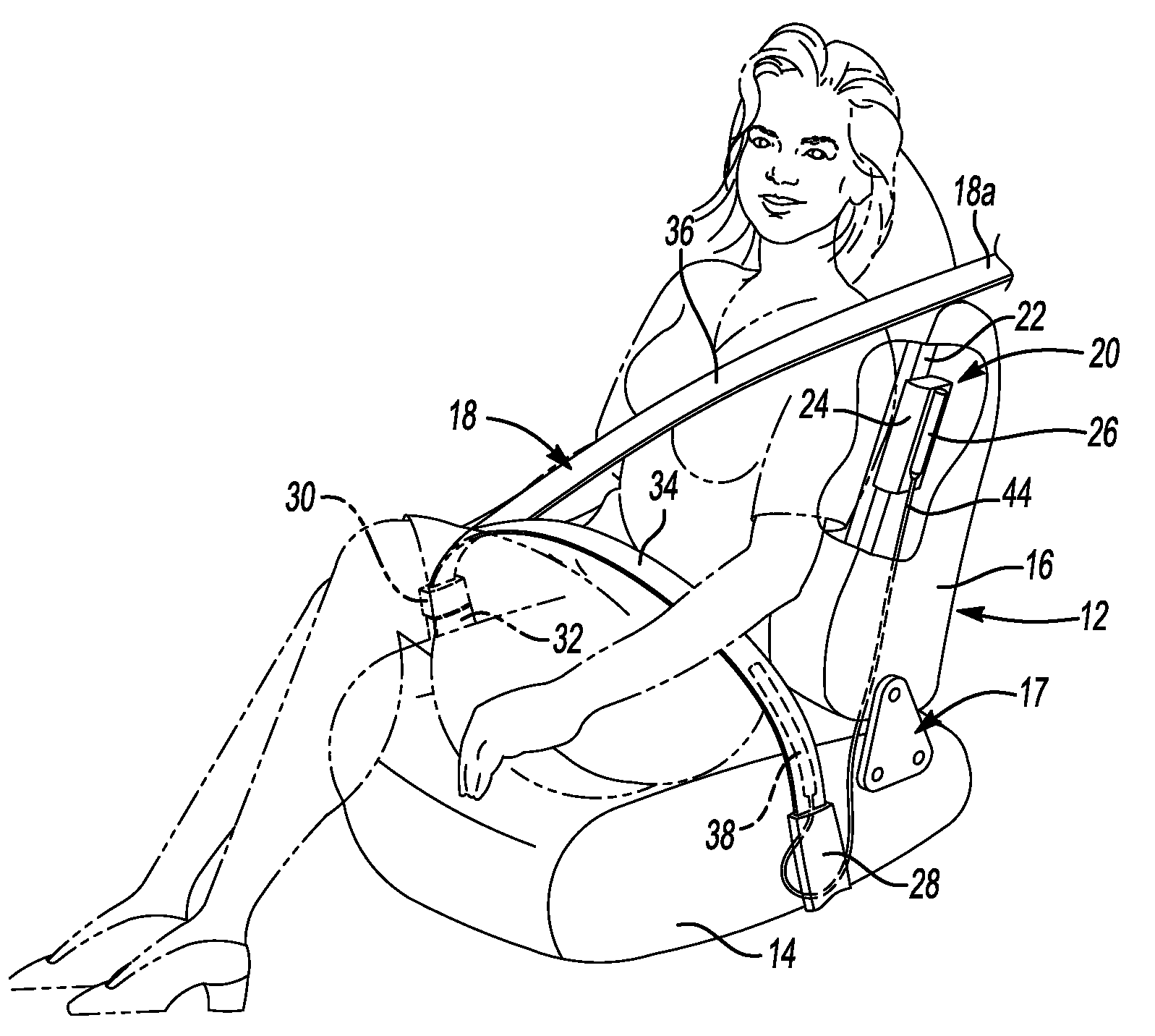
[0009]The seat back-mounted side airbag module provides protection for the thorax region of a seat occupant while the inflatable portion of the lap belt provides protection for the occupant's pelvis region. Because the pelvis protection airbag is incorporated into the lap belt rather than being located inside of or adjacent to the lower seat back, the lower seat back remains free for a folding mechanism or other device mounted in the lower portion of seat back frame. Utilizing the gasses released by the inflator in the side airbag module to also inflate the lap belt inflatable portion simplifies the design and construction of the integrated side impact protection system.
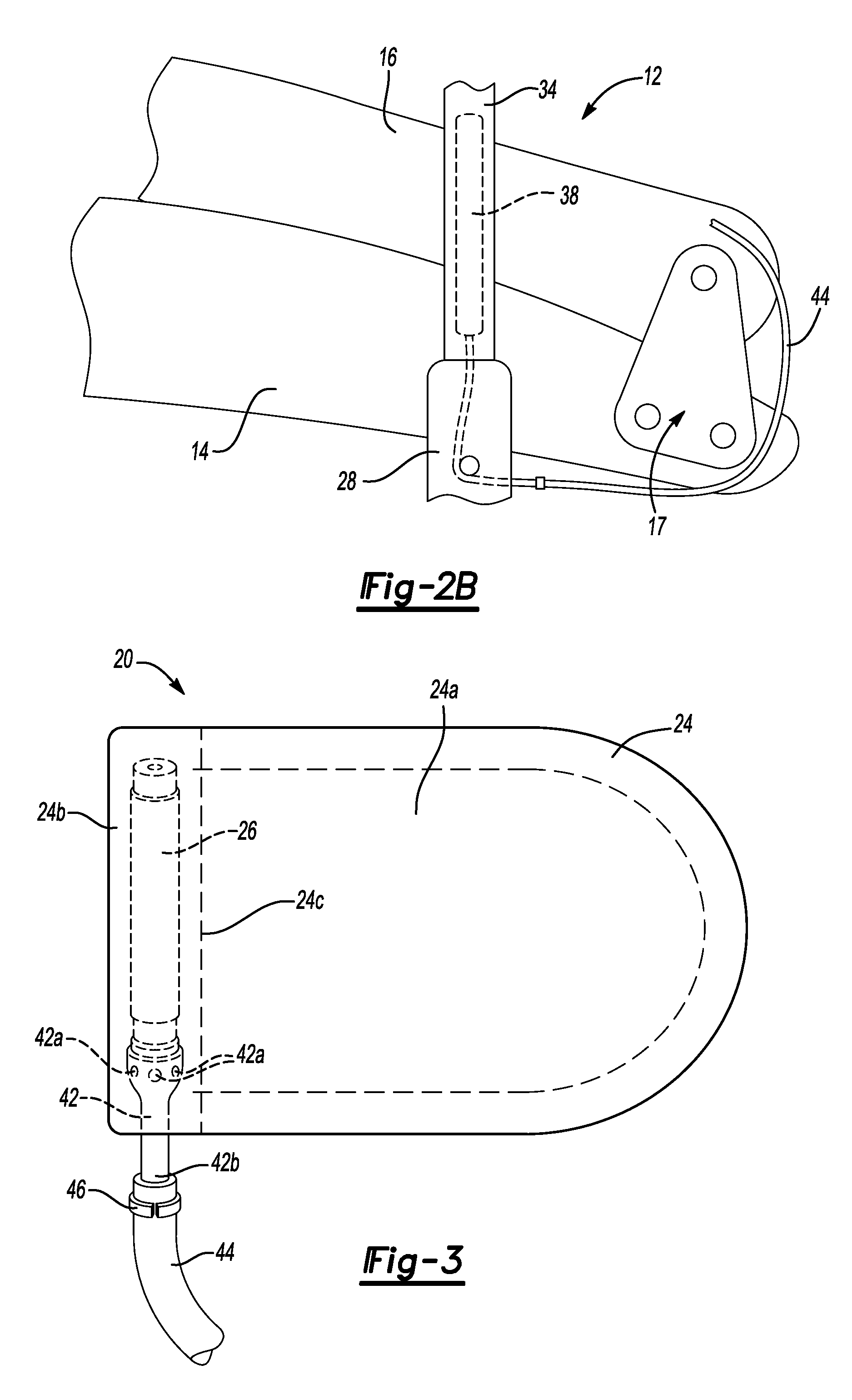
[0011]In an embodiment of the invention, first and second connection fittings are located along the gas conduit to provide a means to easily assemble the components. First and second halves of an optically scannable code are imprinted on the two connection fittings so that the code may be read by an optical scanner only when the two fittings are properly connected with one another. This provides a method for monitoring and ensuring proper assembly.

Problems solved by technology

In some side impact situations, a thorax airbag of the type of side airbag described above may not offer an optimum level of protection for the seat occupant's pelvic region.
A possible issue with this lower mounting position is that may conflict with certain seat features, such as a fold-flat mechanism, that occupy the same location on the seat frame need for the side airbag.

Method used


Image

  • Integrated side airbag and inflatable belt
  • Integrated side airbag and inflatable belt
  • Integrated side airbag and inflatable belt

Examples


Embodiment Construction

[0018]By way of example, a system and method for implementing the present invention is described below. The system and methodology may be adapted, modified or rearranged to best fit a particular implementation without departing from the scope of the present invention.

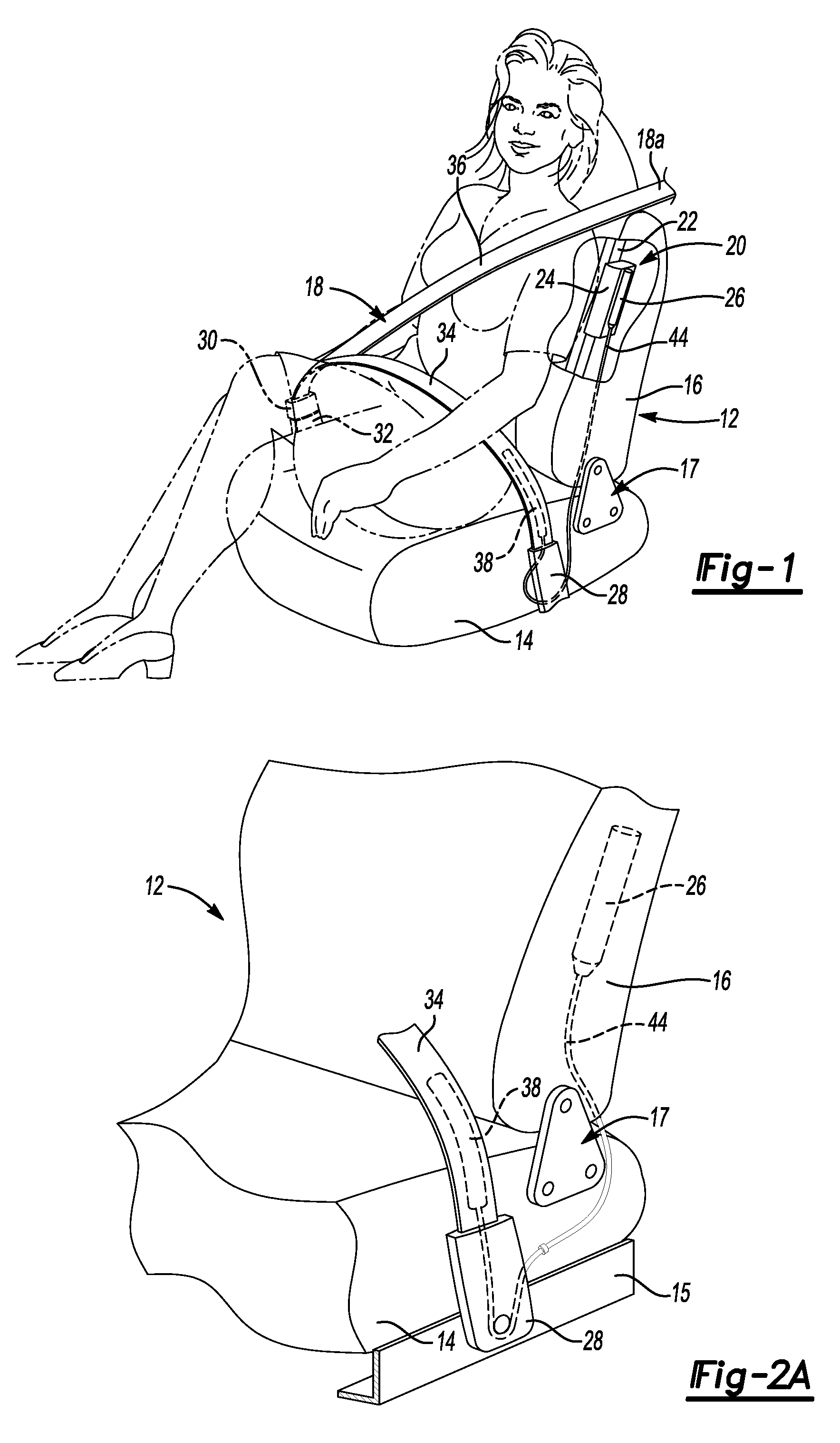
[0019]Referring to FIGS. 1, 2A, and 2B, a vehicle seat 12 is shown that incorporates an occupant protection system according to one embodiment of the invention. Seat 12 generally comprises a seat bottom 14 and a seat back 16. Seat 12 may be attached to a floor of the vehicle by means of floor rails 15 and may be movable forward and rearward along the rails as is well known in the automotive interiors art.

[0020]Seat back 16 is connected with seat bottom 14 by a folding mechanism (generally indicated at 17) for movement between an upright seating position shown in FIG. 1 an 2A and a fold-flat configuration shown in FIG. 2B. The folding movement of seat back 16 relative to seat bottom 14 may be accomplished by a powered sy...


PUM


Abstract

A vehicle seat and integrated side impact protection system includes a seat bottom, a seat back movably attached to the seat bottom, and a fold-flat mechanism within a lower portion of the seat back for permitting movement of the seat back between a seating configuration and a fold-flat configuration. An airbag module is located within an upper portion of the seat back adjacent the outboard side thereof and includes a side airbag and an inflator supplying inflation gasses. A lap belt extends between inboard and outboard sides of the seat and has an inflatable portion adjacent the outboard side of the seat. A gas conduit extends between the airbag module and the lap belt for conducting gasses released by the inflator to the inflatable portion of the lap belt. The gas conduit has a flexible portion permitting folding movement of the seat back.

Description

BACKGROUND[0001]1. Field[0002]The present invention relates generally to occupant restraint systems for automotive vehicles and more particularly to an integrated side-impact airbag and inflatable seat belt system.[0003]2. Background Art[0004]Side airbag systems for automotive vehicles are well known. Current side airbag systems typically include an airbag module mounted to a seat back frame, usually adjacent the outboard side of the seat back. Such airbag modules include an airbag stored in a deflated condition and an inflator that provides gasses to inflate the airbag when triggered by an impact or roll-over sensor. When inflated, the side airbag expands to be positioned between the door, B-pillar, or vehicle side wall adjacent the seat and the seat occupant's thorax, arm, and / or shoulder regions. See, for example, U.S. Patent Application US 2006 / 0012155 A1, the disclosure of which is incorporated herein by reference.[0005]In some side impact situations, a thorax airbag of the typ...

Claims


Application Information

Patent Timeline
IPC IPC(8): B60R21/20
CPCB60R21/18B60R21/207B60R21/26B60R2021/2612
Inventor RYAN, SEAN TIMOTHYVEGGIAN, ERIC D.
Owner FORD GLOBAL TECH LLC
Learn More