
Ophthalmologic measuring apparatus

a technology of ophthalmologic measuring and measuring equipment, which is applied in the field of ophthalmologic measuring equipment, can solve the problems of not being able to say that the demands relating to the judgment of the state of dry eye are sufficiently satisfied, and achieve the effect of meaningful measurement and facilitation of the judgment of the degree of dry ey

Inactive Publication Date: 2010-03-16
KK TOPCON
View PDF7 Cites 9 Cited by
  • Summary
  • Abstract
  • Description
  • Claims
  • Application Information

AI Technical Summary

Benefits of technology

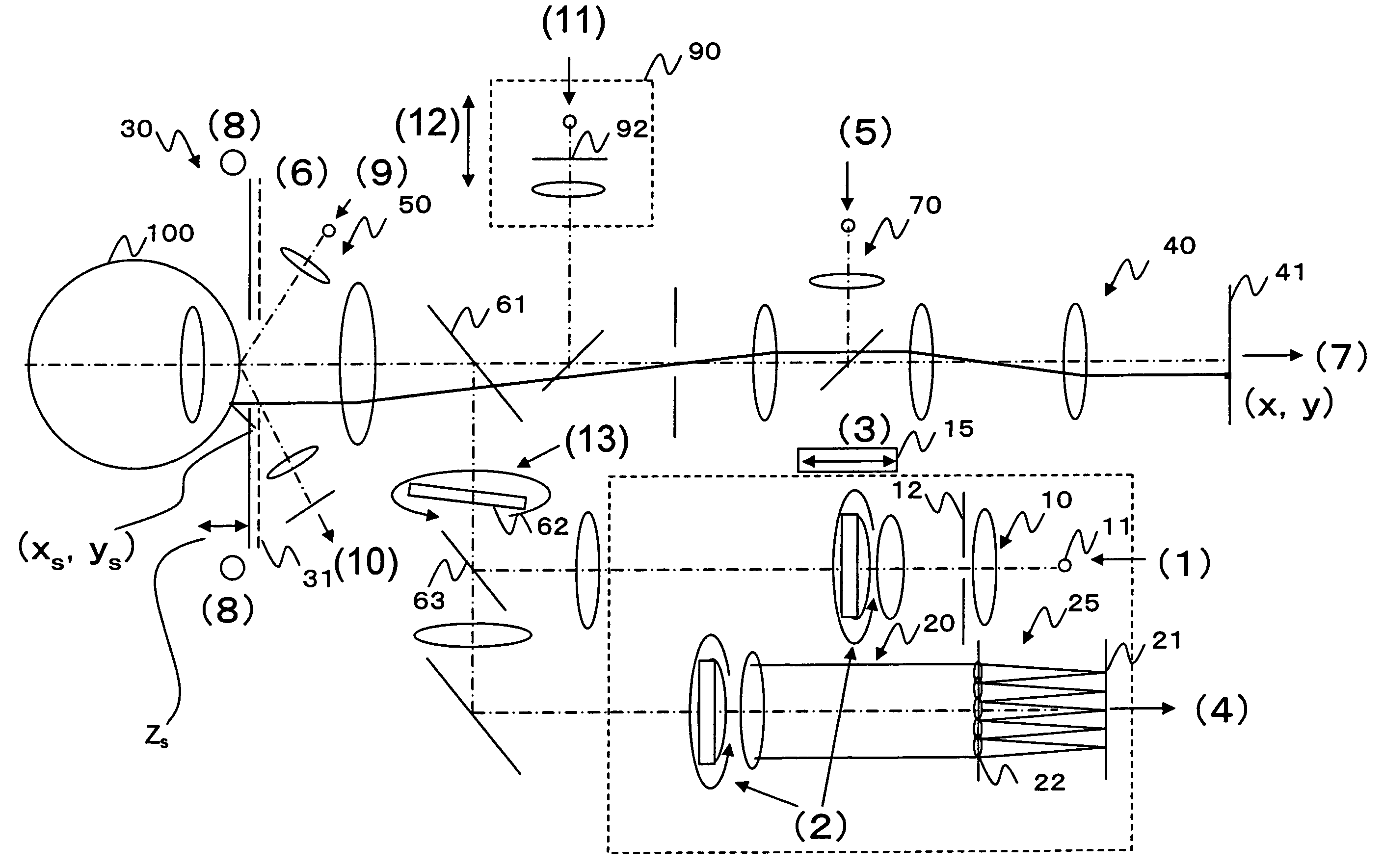
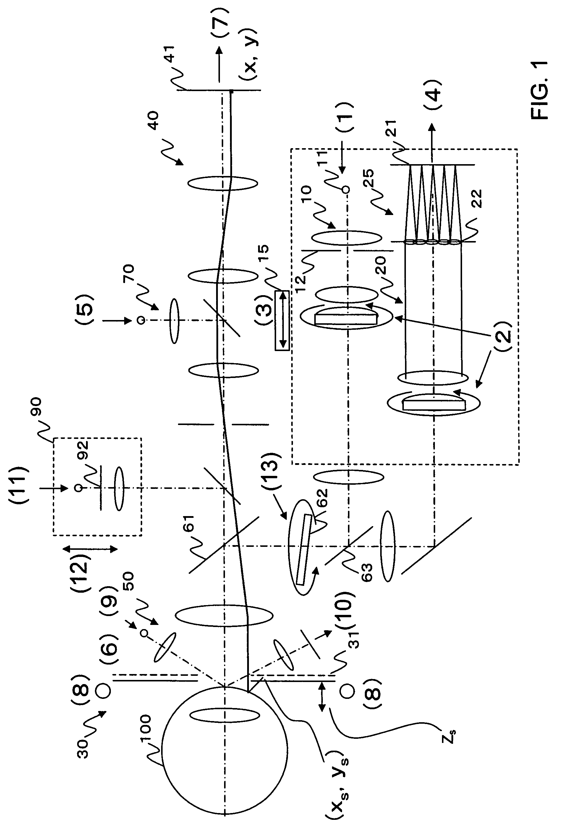
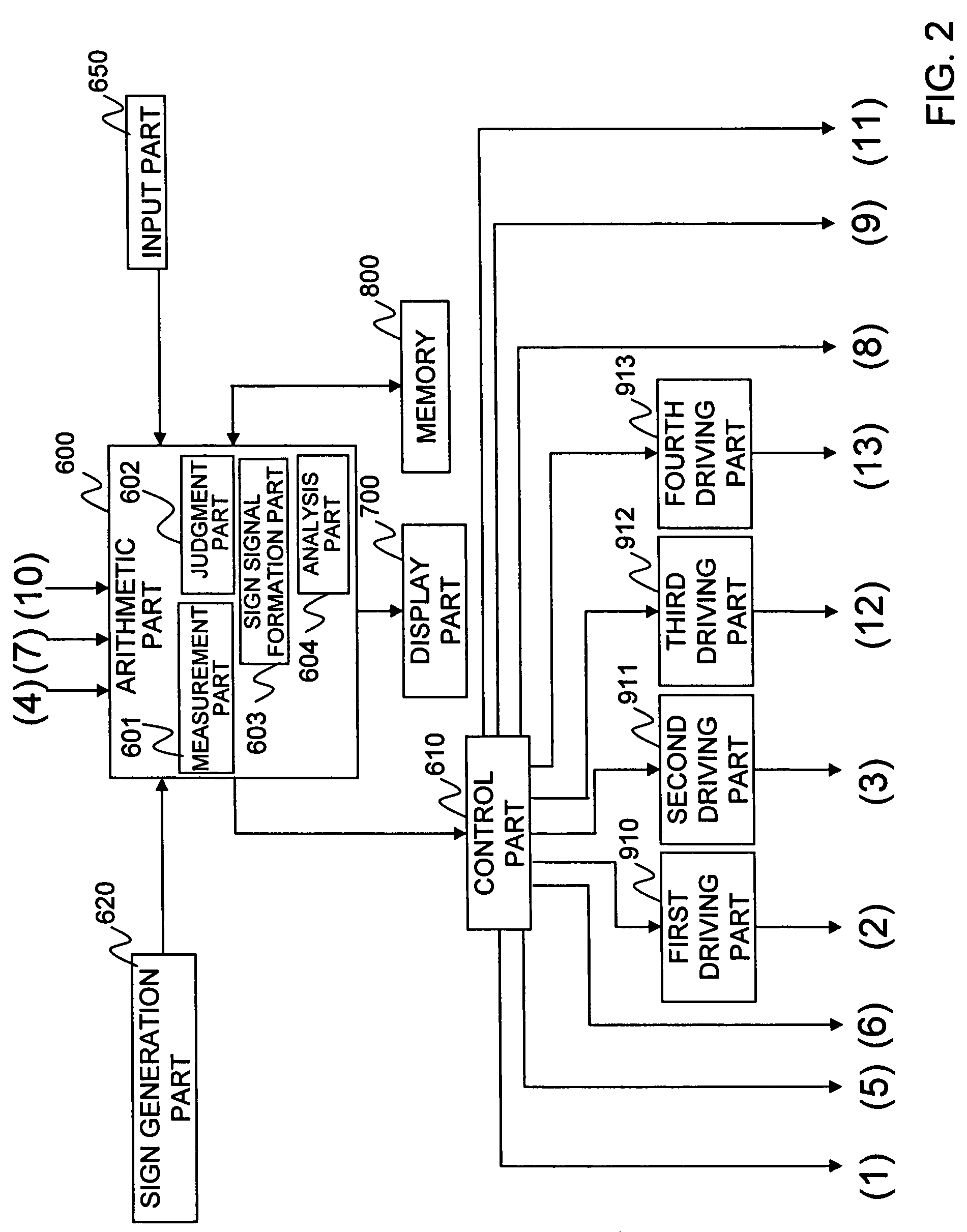
The invention is an ophthalmologic measuring apparatus that can measure the optical characteristics of a subject's eye while they blink naturally or are encouraged to blink at specific intervals. This allows for easier judgment of dry eye and meaningful measurement. Additionally, the apparatus includes an analysis part that can assist with the diagnosis and automated diagnosis of dry eye. The technical effects of the invention are improved accuracy and efficiency in measuring and diagnosing dry eye.

Problems solved by technology

However, in the related art, merely the time change of the ocular aberration is seen, and as the ophthalmologic measuring apparatus used for the clinic of dry eye, it can not be said that demands relating to the judgment of the state of dry eye are sufficiently satisfied.

Method used


Image

  • Ophthalmologic measuring apparatus
  • Ophthalmologic measuring apparatus
  • Ophthalmologic measuring apparatus

Examples


first embodiment

[0081]FIG. 3 shows a measurement flowchart of a first embodiment.

[0082]In the first embodiment, blink interval data by a blink sign is measured.

[0083]The ophthalmologic measuring apparatus may be constructed to select one of a corneal wavefront measurement mode, an ocular wavefront measurement mode and a both-wavefront measurement mode of a cornea and an eyeball, or may be constructed to be capable of performing measurement in one of or plurality of these modes.

[0084]When the subject moves to a measurement position and the measurement is started, the ophthalmologic measuring apparatus is aligned at a position where the eye can be measured (S101). The alignment may be manually or automatically performed. For the wavefront aberration measurement, it is necessary to fix the positions of the cornea and / or the subject eye (retina, ocular fundus, etc.) and the ophthalmologic measuring apparatus within a specified range. The ophthalmologic measuring apparatus is manually or automatically c...

second embodiment

[0092]FIG. 4 shows a measurement flowchart of a second embodiment.

[0093]In the second embodiment, natural blink interval data are measured (blink automatic detection). That is, measurement is performed in a period in which the subject naturally blinks, and a change in aberration is extracted with respect to a common time from the blink.

[0094]The ophthalmologic measuring apparatus may be constructed to be capable of selecting one of the corneal wavefront measurement mode, the ocular wavefront measurement mode, and the both-wavefront measurement mode of the cornea and eye ball, or may be constructed to be capable of performing measurement in one of or plurality of these modes.

[0095]When the subject moves to a measurement position and the measurement starts, the ophthalmologic measuring apparatus is aligned to the position where the eye can be measured (S201). This alignment may be manually or automatically performed. For the wavefront aberration measurement, it is necessary to fix pos...


PUM


Abstract

A subject is placed in a more natural state or is encouraged to blink at specified intervals to obtain a measurement result under a fixed condition, and the judgment of the degree of dry eye is facilitated. A measurement part obtains, based on a reflected light flux from a subject eye, optical characteristic data of a two-dimensional vector form representing the time course of each optical characteristic of the subject eye in an blink interval from a certain blink to a next blink with respect to the first to the nth blink intervals. An analysis part one-dimensionally arranges each of the optical characteristic data with respect to the first to the nth blink intervals measured by the measurement part, and arranges the one-dimensional arrangement of the optical characteristic in a p-th blink interval at a p column to create a two-dimensional array, and performs a principal component analysis processing on the two-dimensional array.

Description

[0001]This application claims priority from Japanese Patent Application No. 2006-093022, filed Mar. 30, 2006, which is incorporated herein by reference in its entirety.BACKGROUND OF THE INVENTION[0002]1. Field of the Invention[0003]The present invention relates to an ophthalmologic measuring apparatus, and particularly to an ophthalmologic measuring apparatus which performs a principal component analysis of ocular characteristic components changing by blinking, and facilitates judgment on the state of an eye, such as dry eye. In an embodiment of the invention, ocular characteristic components are obtained especially as optical characteristic components such as Zernike polynomials, optical characteristic data obtained plural times in an interval from the start point of timing when a blink starts to a point when a next blink starts are arranged longitudinally, and principal component processing is performed on the longitudinally arranged data.[0004]2. Background Art[0005]Hitherto, as ...

Claims


Application Information

Patent Timeline
Patent Type & Authority Patents(United States)
IPC IPC(8): A61B3/14
CPCA61B3/101
Inventor HIROHARA, YOKOMIHASHI, TOSHIFUMI
Owner KK TOPCON
Learn More