Hip joint device

a hip joint and medical device technology, applied in the field of hip joint medical devices, can solve the problems of deteriorating joint function, decreased synovial fluid, and decreased effectiveness of articular cartilage as shock absorber, and achieve the effect of reducing the risk of hip joint dislocation

Active Publication Date: 2021-05-11
FORSELL PETER
View PDF16 Cites 0 Cited by
  • Summary
  • Abstract
  • Description
  • Claims
  • Application Information

AI Technical Summary

Benefits of technology

[0009]A medical device for implantation in a hip joint of a patient is provided. The medical device is adapted to be fixated to the pelvic bone of the patient. The medical device comprises an inner and an outer surface, wherein a contacting portion, of said inner surface is spherical and adapted to face the center of the hip joint when said medical device is implanted. The medical device is adapted to receive a caput femur or a prosthetic replacement therefor having a spherical portion, wherein said medical device comprises at least one extending portion, extending said contacting portion of said inner surface such that said at least one extending portion clasps said spherical portion of said caput femur, or a prosthetic replacement therefor, such that said spherical portion is restrained in said medical device. Restraining the caput femur in the medical device reduces the risk that the hip joint dislocates when in use by the patient.
[0037]According to another embodiment, the extending portion, when implanted, is adapted to be placed such as to restrict the motion range of the hip joint, and wherein said extending portion is adapted to be placed such that adduction is restricted more degrees than flexion.

Problems solved by technology

There are both natural and pathological processes leading to deteriorated joint function.
With age and wear, the articular cartilage becomes less effective as a shock absorber and a lubricated surface.
This abnormal wearing of the cartilage also results in a decrease of the joints lubricating fluid called Synovial fluid.
To get access to the joint, the supporting Capsule attached to Femur and Ilium needs to be penetrated, making it difficult to get a fully functional joint after the surgery.

Method used


Image

  • Hip joint device
  • Hip joint device
  • Hip joint device

Examples


Embodiment Construction

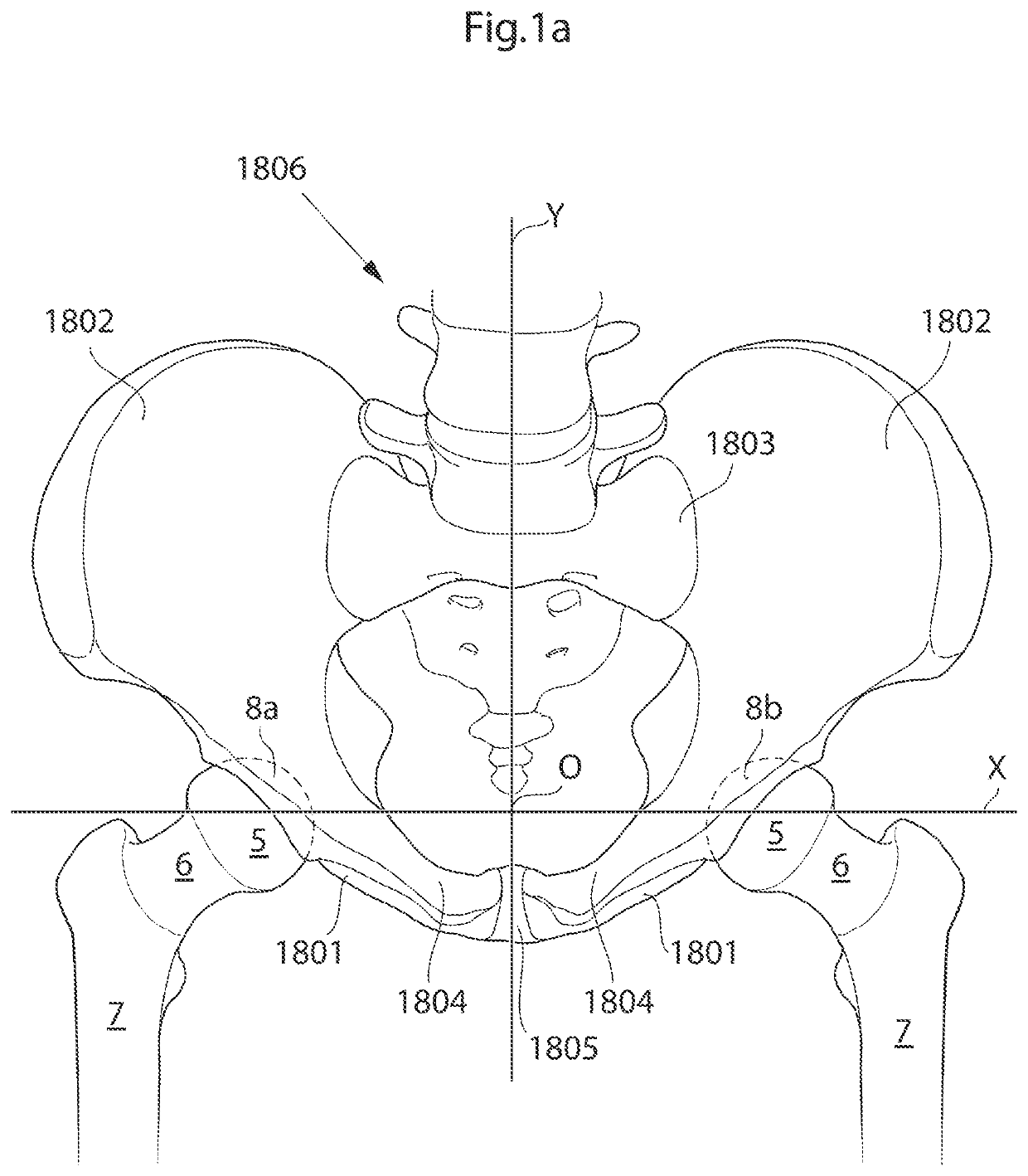
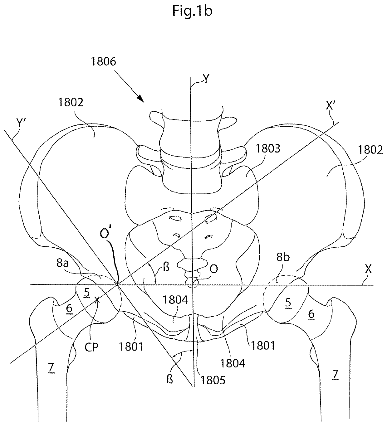
[0109]The hip joint is a synovial ball and socket joint which permits a large motion range for allowing a plurality of different movements of the lower limb. From a neutral position the following movements of the hip joint are normally possible: Lateral or external rotation, 30° with the hip extended, 50° with the hip flexed, medial or internal rotation 40°, extension or retroversion 20°, flexion or anteversion 140°, abduction 50° with hip extended, 80° with hip flexed, adduction 30° with hip extended, 20° with hip flexed.

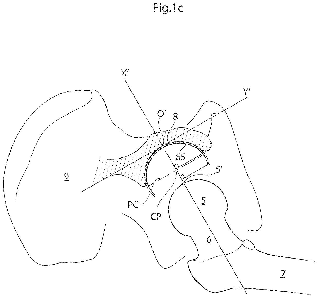
[0110]When replacing the natural hip joint with a prosthetic hip joint, the depth of the prosthetic acetabulum will affect the motion range, the deeper the acetabulum bowl is made the more restrictive it is to the motion range. A deeper bowl has the advantage of reducing the risk of hip joint luxation, the risk of which is a major drawback with prosthetic hips of today.

[0111]The anatomy of the hip joint and its surroundings is further disclosed in: Marieb et al., H...


PUM


Abstract

A medical device for implantation in a hip joint and fixated to the pelvic bone of a patient is provided. The medical device has an inner and an outer surface. A contacting portion, of the inner surface is spherical and adapted to face the center of the hip joint when the medical device is implanted. The medical device is adapted to receive a caput femur or a prosthetic caput femur which has a spherical portion. The medical device has at least one extending portion, extending the contacting portion of the inner surface such that the at least one extending portion clasps the spherical portion of the caput femur or a prosthetic caput femur, such that the spherical portion is restrained in the medical device. Restraining the caput femur in the medical device reduces the risk that the hip joint dislocates when in use by the patient.

Description

[0001]This application is the U.S. national phase of International Application No. PCT / SE2010 / 050800, filed 12 Jul. 2010, which designated the U.S. and claims the benefit of U.S. Provisional Nos.: 61 / 229,755, filed 30 Jul. 2009; 61 / 229,738 filed 30 Jul. 2009; 61 / 229,739 filed 30 Jul. 2009; 61 / 229,743 filed 30 Jul. 2009; 61 / 229,745 filed 30 Jul. 2009; 61 / 229,746 filed 30 Jul. 2009; 61 / 229,747 filed 30 Jul. 2009; 61 / 229,748 filed 30 Jul. 2009; 61 / 229,751 filed 30 Jul. 2009; 61 / 229,752 filed 30 Jul. 2009; 61 / 229,761 filed 30 Jul. 2009; 61 / 229,767 filed 30 Jul. 2009; 61 / 229,778 filed 30 Jul. 2009; 61 / 229,786 filed 30 Jul. 2009; 61 / 229,789 filed 30 Jul. 2009; 61 / 229,796 filed 30 Jul. 2009; 61 / 229,735 filed 30 Jul. 2009; and which claims priority to Swedish Application Nos.: 0900981-2 filed 10 Jul. 2009; 0900957-2 filed 10 Jul. 2009; 0900958-0 filed 10 Jul. 2009; 0900959-8 filed 10 Jul. 2009; 0900960-6 filed 10 Jul. 2009; 0900962-2 filed 10 Jul. 2009; 0900963-0 filed 10 Jul. 2009; 0900965...

Claims


Application Information

Patent Timeline
Patent Type & Authority Patents(United States)
IPC IPC(8): A61F2/32A61F2/30A61F2/36A61F2/34A61F2/46A61F2/08
CPCA61F2/3609A61F2/34A61F2/08A61F2002/305A61F2002/30079A61F2002/30364A61F2002/30462A61F2002/30479A61F2002/30492A61F2002/30505A61F2002/30561A61F2002/30565A61F2002/30566A61F2002/30568A61F2002/30594A61F2002/30617A61F2002/30822A61F2002/30828A61F2002/3208A61F2002/3233A61F2002/3241A61F2002/3401A61F2002/3403A61F2002/3417A61F2002/3443A61F2002/3446A61F2002/3493A61F2002/4698
Inventor FORSELL, PETER
Owner FORSELL PETER
Why Eureka
Try Eureka