
Device for detecting state of thermal degradation of exhaust purifying catalyst

a technology of thermal degradation and exhaust purification catalyst, which is applied in the direction of electrical control, instruments, machines/engines, etc., can solve the problems of gradual degradation of catalyst purification performance and the progress of thermal degradation of exhaust purifying catalyst, and achieve the effect of improving detection accuracy

Inactive Publication Date: 2009-08-04
TOYOTA JIDOSHA KK
View PDF4 Cites 5 Cited by
  • Summary
  • Abstract
  • Description
  • Claims
  • Application Information

AI Technical Summary

Benefits of technology

This approach improves the accuracy of detecting thermal degradation by reflecting the actual variation in the rate of progress, enabling timely identification of catalyst defects and maintaining exhaust purifying performance.

Problems solved by technology

In other words, thermal degradation of exhaust purifying catalyst proceeds, and catalyst purifying performance degrades gradually.

Method used


Image

  • Device for detecting state of thermal degradation of exhaust purifying catalyst
  • Device for detecting state of thermal degradation of exhaust purifying catalyst
  • Device for detecting state of thermal degradation of exhaust purifying catalyst

Examples


Embodiment Construction

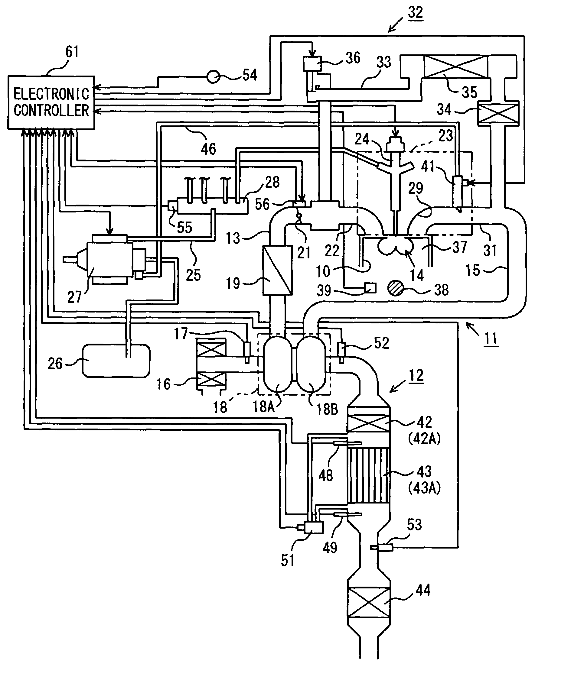
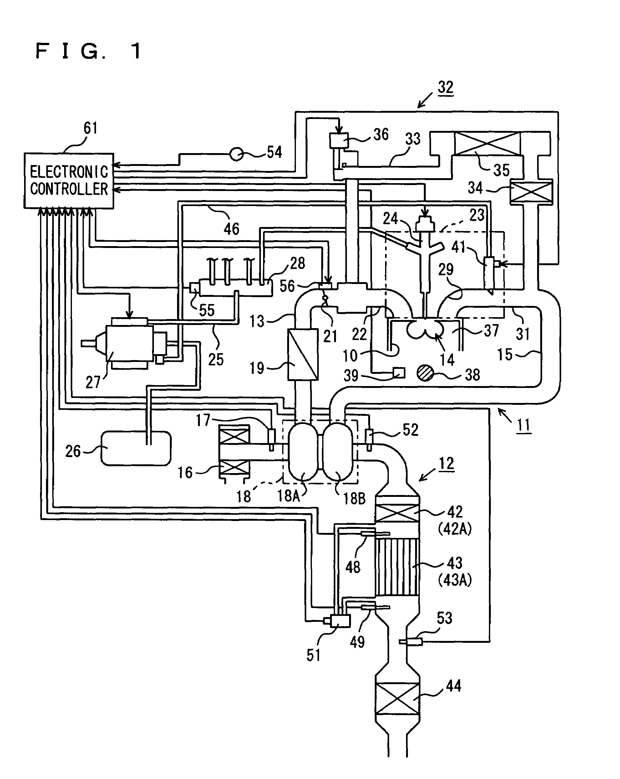
[0031]In the following, an embodiment of the present invention will be described with reference to the figures. FIG. 1 shows configurations of a multi-cylinder diesel engine (hereinafter simply referred to as the engine) as an internal combustion engine and its exhaust purifier 12, to which the present embodiment is applied.

[0032]Engine 11 mainly includes an intake passage 13, a combustion chamber 14 provided in each cylinder 10, and an exhaust passage 15. At the uppermost stream of intake passage 13, an air cleaner 16 for purifying air introduced to intake passage 13 is provided. In engine 11, an air flow meter 17 for detecting air flow rate in intake passage 13, a compressor 18A of a turbo charger 18, an inter cooler 19, and an intake throttle valve 21 are arranged in this order to the downstream side of intake air flow, from air cleaner 16. Intake passage 13 is branched at an intake manifold 22 provided downstream of intake throttle valve 21 along the intake air flow, and connect...


PUM


Abstract

An electronic controller integrates a rate of progress dK of thermal degradation of exhaust purifying catalyst at every predetermined time period, to calculate degree of thermal degradation K of the exhaust purifying catalyst, when the state of thermal degradation of the exhaust purifying catalyst is to be detected. By comparing the degree of thermal degradation K with a defect determining value S, whether the exhaust purifying catalyst is defective because of thermal degradation or not is determined. In calculating the degree of thermal degradation K, the electronic controller calculates the rate of progress dK of thermal degradation in the predetermined time period based on the integrated value of rate of progress dK of thermal degradation up to the last time (degree of thermal degradation K) and on the temperature T of exhaust purifying catalyst at that time, and adds the same to the integrated value up to the last time.

Description

[0001]This nonprovisional application is based on Japanese Patent Application No. 2005-112870 filed with the Japan Patent Office on Apr. 8, 2005, the entire contents of which are hereby incorporated by reference.BACKGROUND OF THE INVENTION[0002]1. Field of the Invention[0003]The present invention relates to a device for detecting a state of thermal degradation of an exhaust purifying catalyst, detecting a state of degradation caused by heat, of an exhaust purifying catalyst arranged in an exhaust passage of an internal combustion engine for purifying exhaust gas.[0004]2. Description of the Background Art[0005]An exhaust purifying catalyst such as an NOx catalyst used for an internal combustion engine gradually degrades by heat through use, and its exhaust purifying function lowers. Therefore, it is important to exactly ascertain the state of thermal degradation of the exhaust purifying catalyst and to address any problem promptly.[0006]For this purpose, various techniques for detect...

Claims


Application Information

Patent Timeline
Patent Type & Authority Patents(United States)
IPC IPC(8): F01N3/00
CPCF01N3/0842F01N3/103F01N11/005F01N13/009F01N13/0097F01N13/0093F01N3/0814F01N2550/02F01N2550/03F02D41/027F02D41/3035Y02T10/47F02B37/00Y02T10/40
Inventor UCHIDA, TAKAHIROMORIKAWA, ATSUSHISUGIYAMA, TATSUMASA
Owner TOYOTA JIDOSHA KK
Learn More