Linear motion guide unit

a technology of motion guide and guide rod, which is applied in the direction of bearings, bearings, shafts and bearings, etc., can solve the problems of too steep crowning profile and however sophisticated construction of crowning profile, and achieve high accuracy, high durability, and effective compliance

Active Publication Date: 2010-03-16
NIPPON THOMPSON
View PDF17 Cites 13 Cited by
  • Summary
  • Abstract
  • Description
  • Claims
  • Application Information

AI Technical Summary

Benefits of technology

[0011]The present invention, therefore, has as its primary object to overcome the problem as described just above and to provide an improved linear motion guide unit of standard design specification available widely in common use, in which a crowning profile is easily made on a raceway groove inclusive of a raceway surface cut on a carriage of a slider that fits over a guide rail inclusive of a guide shaft for relative movement each other. More particular, the present invention provides a linear motion guide unit improved in high accuracy and long-lasting service life and in which a crowning profile is not more than one tenth in depth compared with the conventional.
[0021]The constructional features recited earlier are preferably suited to the linear lotion guide unit that is comprised of the guide rail including the guide shaft, and the slider movable relatively to the guide rail by virtue of the rolling elements of ball or roller, which run through the recirculation circuit in the slider. The constructional features are also effective in complying with the needs of high accuracy as well as high durability. The constructional features defined earlier are further beneficial to rendering the working of the crowning portion more easier, making the sliding performance of the slider higher, and raising the traveling accuracy and durability in the linear motion guide unit, despite of the improvement done at very tiny parts in the ingress / egress areas of the load race at the forward and aft ends of the carriage.
[0022]In the linear motion guide unit of the present invention, the carriage is made therein with a lengthwise bore into which a lubricant impregnated sleeve of C-shape in cross section fits to provide a return passage that helps improve the rolling performance of the rolling elements.

Problems solved by technology

The crowning profile is however sophisticated in construction, involving complex computer modeling recipes and highly refined skill for machining operation.
This means that the crowning profile is too steep to deal with highly accurate requirements.

Method used


Image

  • Linear motion guide unit
  • Linear motion guide unit
  • Linear motion guide unit

Examples


Embodiment Construction

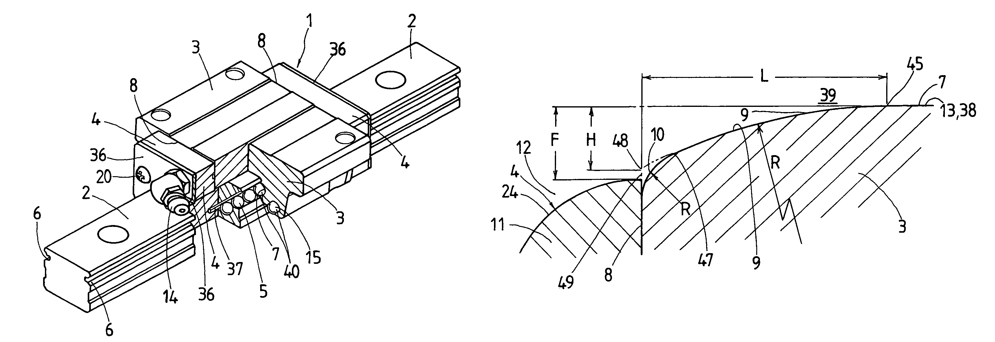
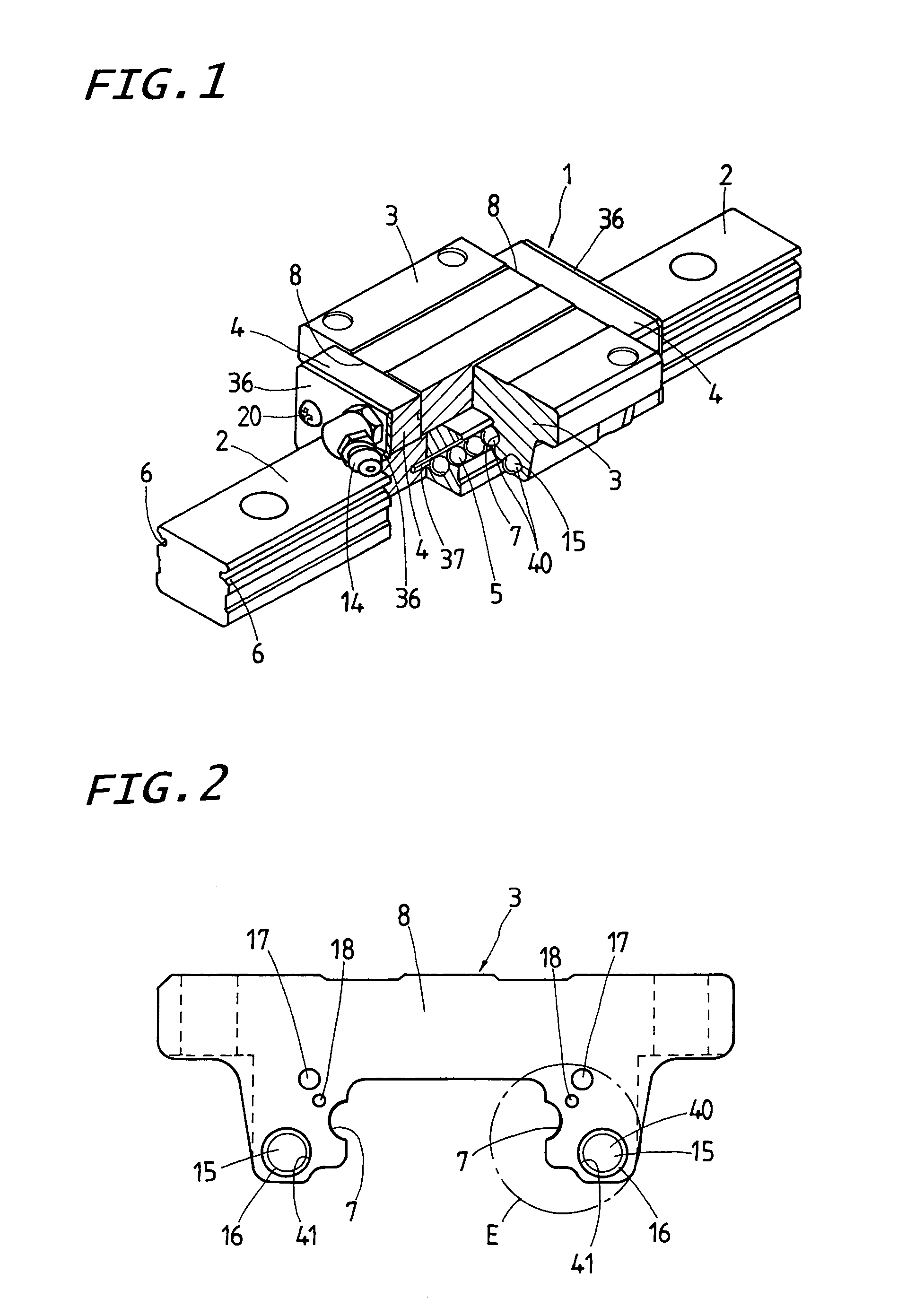
[0037]The linear motion guide unit according to the present invention discussed later is adapted for extensive use in a relative sliding system of a variety of machinery including machine tools, semiconductor fabricating machines, precise instruments, and so on, which looks increasingly for high traveling accuracy as well as high durability even under high-speed, high-acceleration / high-deceleration operational environment.

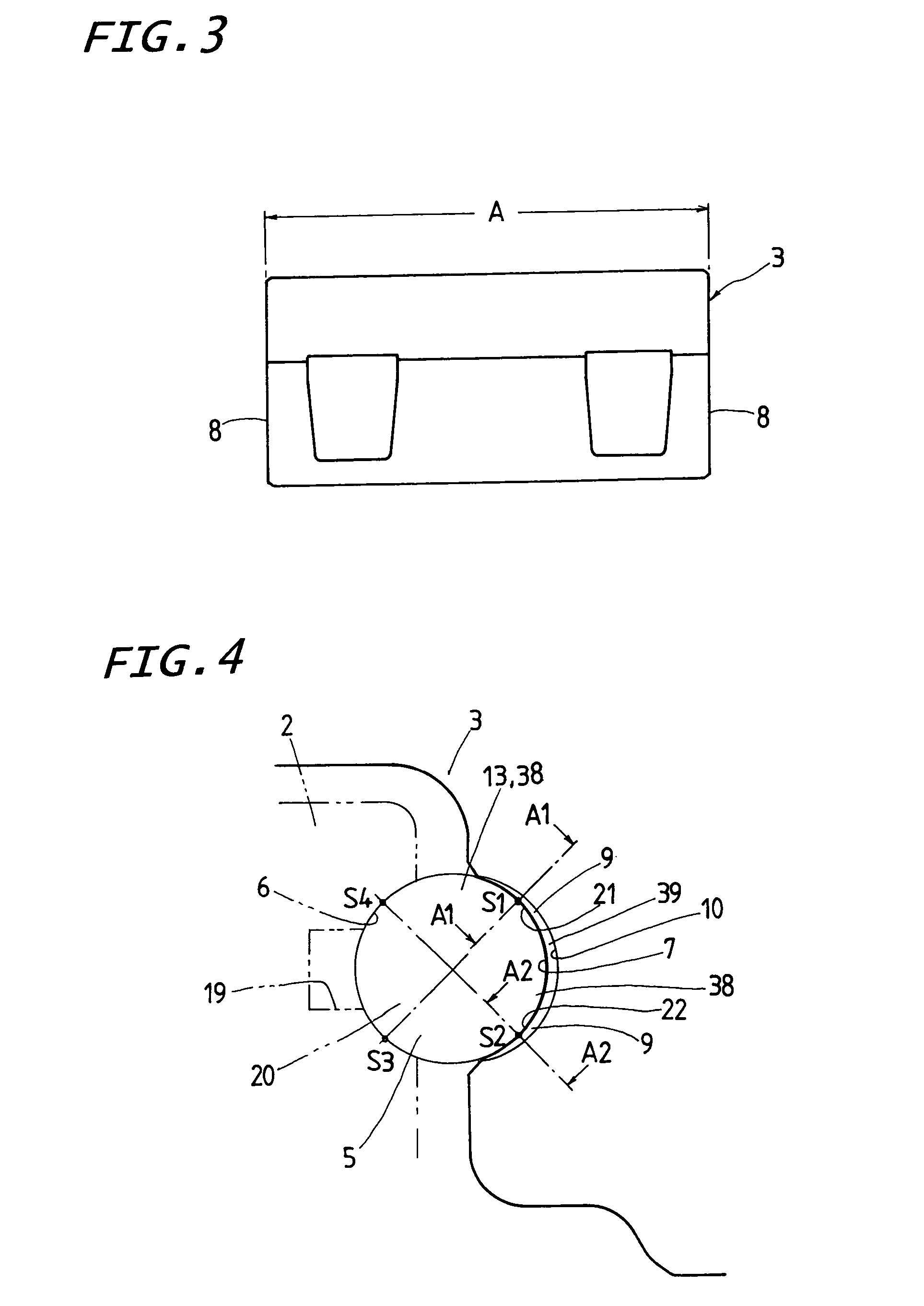
[0038]A preferred embodiment of the linear motion guide unit according to the present invention will be hereinafter described with reference to the accompanying drawings. Here is shown a linear motion guide unit of the most common type in which there is provided a recirculation circuit 40 allowing more than one rolling element 5 of ball to run through there in a circulating manner while a slider 1 fits over a guide rail 2 for sliding movement relative to each other. Nevertheless, it will be appreciated that the linear motion guide unit is not limited to the fashion...


PUM


Abstract

A linear motion guide unit is provided in which a crowning portion available extensively for standard specification is made easily. The crowning portion is comparatively small in depth, and rich in high accuracy and high durability. A raceway groove for a load race in a carriage is made at an ingress / egress area thereof with the crowning portion of a curved profile that varies gently to allow the rolling element to move in and out of the load race with smoothness. The carriage is provided at the forward and aft ends of the raceway groove with rounded bevels, which are made in a curved contour merging into the associated crowning portion without causing any discontinuity at a junction of the rounded bevel with the crowning portion.

Description

FIELD OF THE INVENTION[0001]The present invention relates to a linear motion guide unit comprised of a guide rail with raceway grooves, and a slider allowed to move on the guide rail by virtue of more than one rolling element.BACKGROUND OF THE INVENTION[0002]Conventionally, there have been well known linear motion guide units of the sort that more than one rolling element is allowed to roll through a recirculation circuit made in a slider. In the prior linear motion guide units of the type constructed as stated earlier, as shown in FIG. 14, a carriage 3 of the slider is generally made thereon with a raceway groove 7 including a raceway surface for the provision of a load race 13. The raceway groove 7 is moreover is made in a crowning profile 43 extending across an ingress area 39, which slopes gently towards any one of forward and aft ends of the carriage 3 so as to allow the rolling elements rolling through with smoothness in and out of the load race 13. With the linear motion guid...

Claims


Application Information

Patent Timeline
Patent Type & Authority Patents(United States)
IPC IPC(8): F16C29/06
CPCF16C29/0604F16C29/0609F16C29/064
Inventor GEKA, TOSHIAKIOGURA, HIDEAKI
Owner NIPPON THOMPSON
Why Eureka
Try Eureka