Device for external fixation strut measurement and real-time feedback
- Summary
- Abstract
- Description
- Claims
- Application Information
AI Technical Summary
Benefits of technology
Problems solved by technology
Method used
Image
Examples
first embodiment
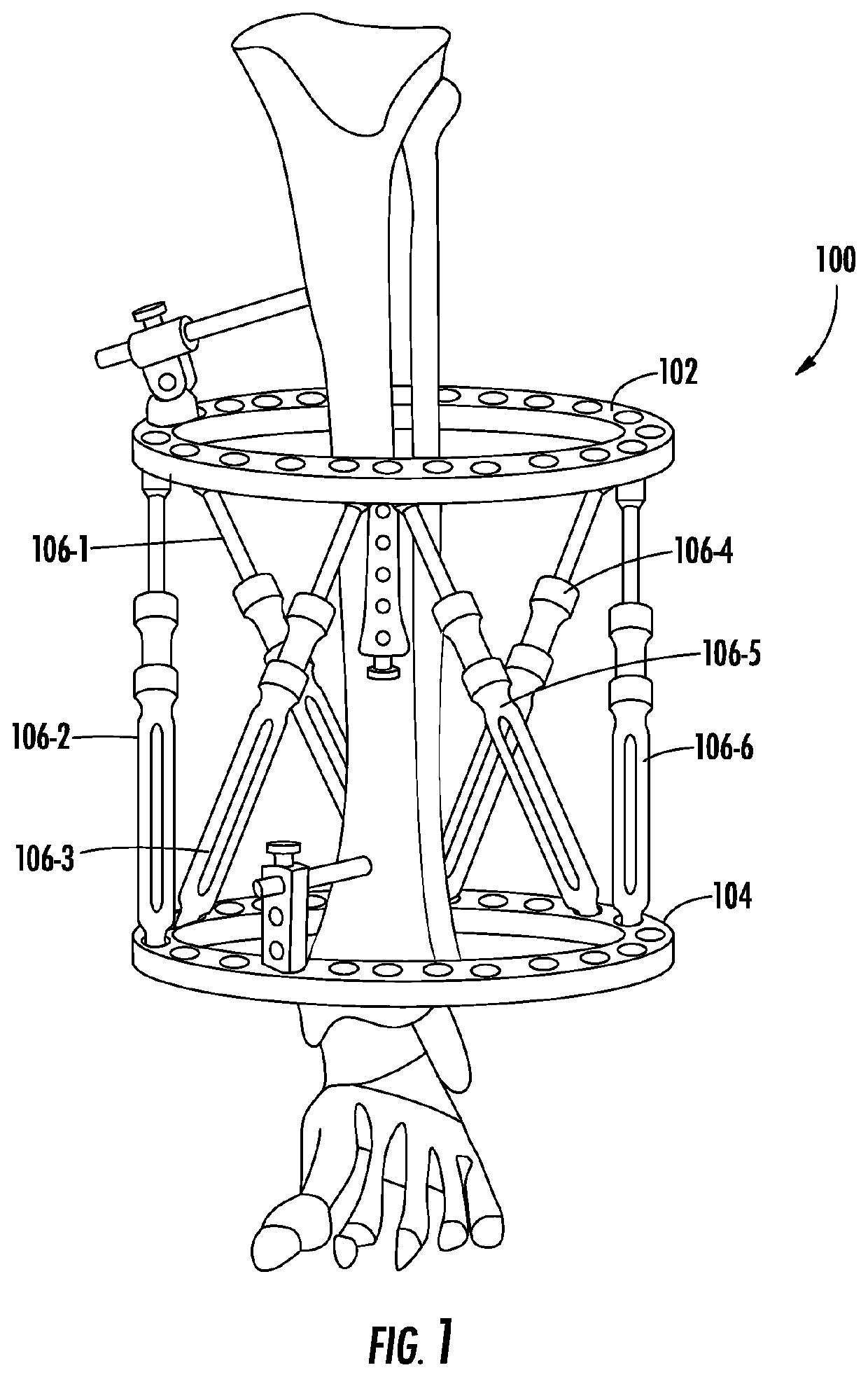
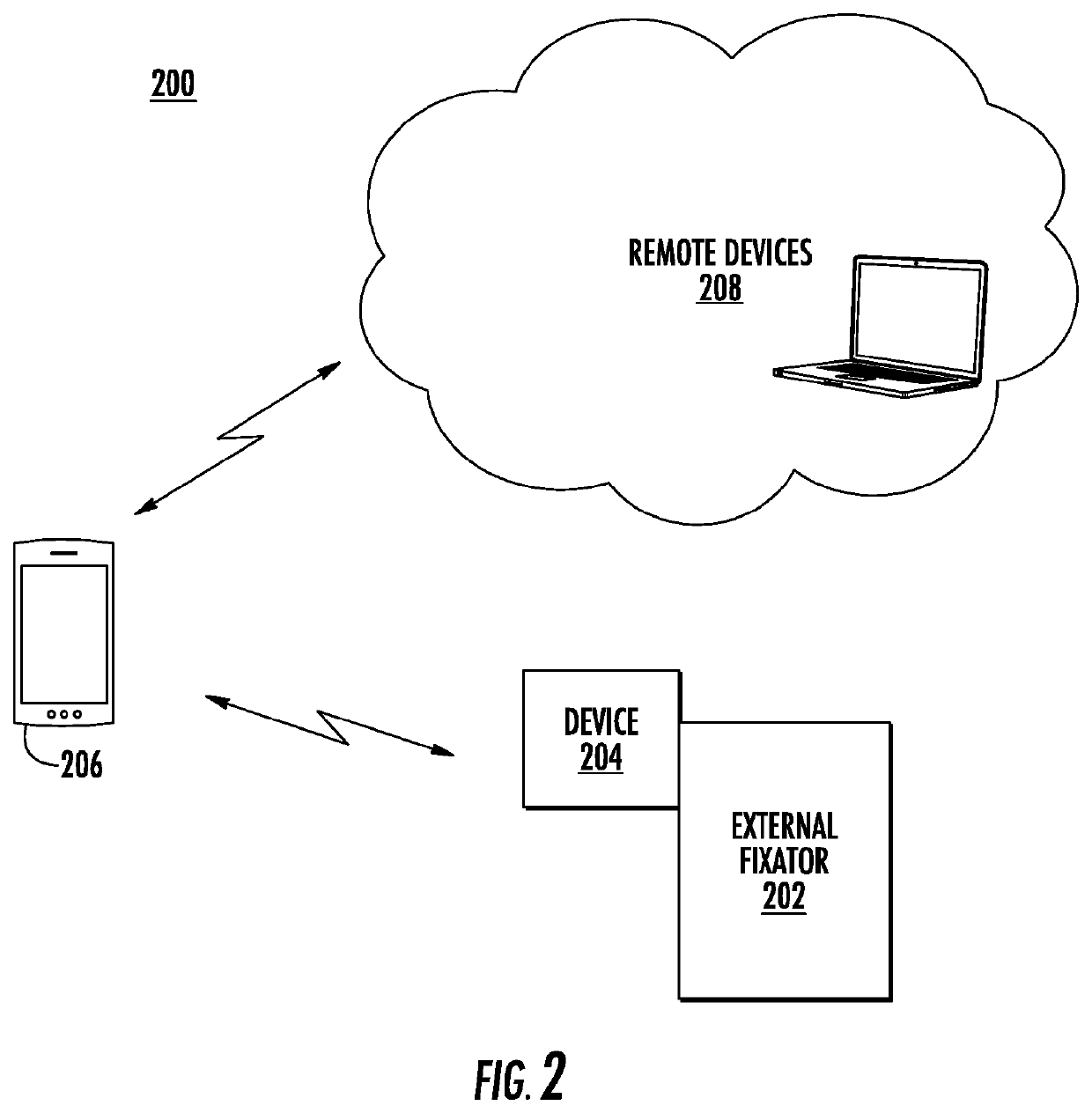
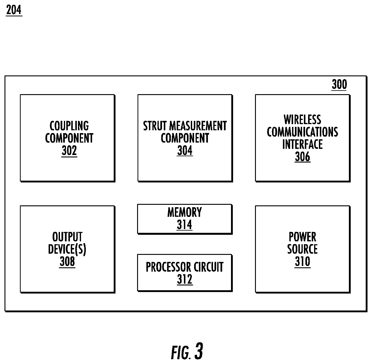
[0101]FIG. 4 illustrates a strut measurement and feedback device 400. The strut measurement and feedback device 400 may represent the strut measurement and feedback device 204 as depicted in FIGS. 2 and 3. As shown in FIG. 4, the strut measurement and feedback device 400 is coupled to a strut 402. The strut 402 can be a strut of the external fixator 202 as depicted in FIG. 2.
[0102]The strut measurement and feedback device 400 may include a high-resolution camera 406. The camera 406 may be used to visualize laser markings (not shown in FIG. 4 for simplicity) on the outside of the strut 402. The camera 406 may also be used to visualize movement of a strut pin (not shown in FIG. 4 for simplicity) positioned within a slot 408 of the strut 402. Multiple images of the strut pin can be captured and analyzed to calculate the motion of the strut pin within the slot 408. In various embodiments, the motion of the strut pin can be analyzed using image processing functionality residing on the st...
second embodiment
[0113]FIG. 5 illustrates a strut measurement and feedback device 500. The strut measurement and feedback device 500 may represent the strut measurement and feedback device 204 as depicted in FIGS. 2 and 3. As shown in FIG. 5, the strut measurement and feedback device 500 is coupled to a strut 502. The strut 502 can be a strut of the external fixator 202 as depicted in FIG. 2.
[0114]The strut measurement and feedback device 500 may represent an alternative arrangement, form factor, or design of the strut measurement and feedback device 400. In various embodiments, the strut measurement and feedback device 500 may include the same or similar components and may provide the same or similar functionalities as the strut measurement and feedback devices 204 and 400. As shown in FIG. 5, the strut measurement and feedback device 500 is positioned over a strut pin 504 that can be used to detect an absolute position of the strut 502 as described above in relation to the strut measurement and fe...
third embodiment
[0118]FIG. 7 illustrates a strut measurement and feedback device 700. The strut measurement and feedback device 700 may represent the strut measurement and feedback device 204 as depicted in FIGS. 2 and 3. As shown in FIG. 7, the strut measurement and feedback device 700 is coupled to a strut 702. The strut 702 can be a strut of the external fixator 202 as depicted in FIG. 2. The strut 702 can include an outer body component 710. Positioned within an interior of the strut 702 can be a rod 704 (e.g., a threaded rod) that can be moved relative to the outer body component 710.
[0119]The strut measurement and feedback device 700 can include an ultrasonic measuring device or component to determine a length of the strut 702 (and / or a position of the rod 704). As shown in FIG. 7, the strut 702 can include an opening or window 706 that can accept an arm or extension component 708 of the strut measurement and feedback device 700. The arm component 708 can be positioned within the opening 706 ...
PUM
 Abstract
Description
Claims
Application Information
 - R&D
- Intellectual Property
- Life Sciences
- Materials
- Tech Scout
- Unparalleled Data Quality
- Higher Quality Content
- 60% Fewer Hallucinations
Browse by: Latest US Patents, China's latest patents, Technical Efficacy Thesaurus, Application Domain, Technology Topic, Popular Technical Reports.
© 2025 PatSnap. All rights reserved.Legal|Privacy policy|Modern Slavery Act Transparency Statement|Sitemap|About US| Contact US: help@patsnap.com


