Vacuum insulated glass (VIG) unit including nano-composite pillars, and/or methods of making the same

a vacuum insulated glass and nano-composite technology, applied in the direction of parallel plane units, layered products, chemistry apparatus and processes, etc., can solve the problems of undesirable high temperature and long heating time of the entire assembly used in the formulation of edge seals b>4, and adversely affect certain low-e coatings

Active Publication Date: 2012-04-12
GUARDIAN GLASS LLC
View PDF2 Cites 55 Cited by
  • Summary
  • Abstract
  • Description
  • Claims
  • Application Information

AI Technical Summary

Benefits of technology

[0016]In certain example embodiments of this invention, a vacuum insulated glass (VIG) unit is provided. First and second substantially parallel, spaced apart glass substrates define a gap therebetween. An edge seal is provided around a periphery of the first and second substrates to form an hermetic seal. A plurality of pillars is provided between the first and second substrates. A high-aspect ratio lamellar coating is provided between said pillars and the first and / or second substrates so as to at least partially offset tensile stresses applied to the first and / or second glass substrates. The gap is provided at a pressure less than atmospheric.
[0017]In certain example embodiments of this invention, a method of making a vacuum insulated glass (VIG) unit is provided. First and second glass substrates are provided. A plurality of pillars are provided on the first glass substrate. The first and second substrates are sealed together (e.g., using at least one edge seal) such that the first and second substrates are in substantially parallel, spaced apart orientation to one another and to define a gap therebetween. The gap is evacuated to a pressure less than atmospheric. A lamellar coating is provided between the pillars and the first and / or second substrates so as to at least partially offset tensile stresses also applied to the first and / or second glass substrates.

Problems solved by technology

Unfortunately, the aforesaid high temperatures and long heating times of the entire assembly utilized in the formulation of edge seal 4 are undesirable, especially when it is desired to use a heat strengthened or tempered glass substrate(s) 2, 3 in the vacuum IG unit.
Moreover, such high processing temperatures may adversely affect certain low-E coating(s) that may be applied to one or both of the glass substrates in certain instances.
Such a significant loss (i.e., 80% loss) of temper strength is of course undesirable.
This may or may not be desirable in some instances.
Even when non-tempered glass substrates are used, the high temperatures applied to the entire VIG assembly may soften the glass or introduce stresses, and partial heating may introduce more stress.
These stresses may increase the likelihood of deformation of the glass and / or breakage.
Moreover, VIG units are subject to extremely large static and dynamic loading as well as thermally induced stresses both during its manufacturing (e.g., during pump down and thermal seal processing) and throughout its service life (e.g., during wind-loads or mechanical and thermal shocks).
The pillar spacers used to mechanically support the gap between the two substrates tend to indent the glass surfaces with which they in contact, thereby creating indented areas from which cracks may propagate and hence weakening the glass structure.
It has been found that it is in the tensile regime that annealed glass is at its weakest state, and it has been found that any surface and bulk flaws in the tensile stress field may develop into cracks that may propagate.
The magnitude of the tensile stress component increases with the inter-pillar spacing, and the likelihood of the cracks forming and ensuing catastrophic breakage increases once the stress field is above the strength of the glass.
Unfortunately, however the VIG process takes place at high temperatures and involves a thermal cycle duration that potentially can de-temper the glass.

Method used


Image

  • Vacuum insulated glass (VIG) unit including nano-composite pillars, and/or methods of making the same
  • Vacuum insulated glass (VIG) unit including nano-composite pillars, and/or methods of making the same
  • Vacuum insulated glass (VIG) unit including nano-composite pillars, and/or methods of making the same

Examples


Embodiment Construction

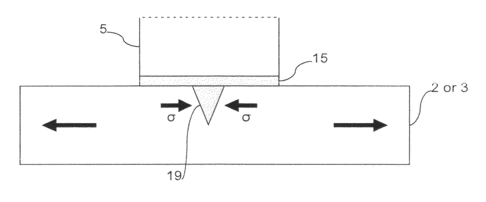
[0031]It will be appreciated that from a structural perspective, it would be advantageous to provide a VIG unit with a high stiffness and high damping behavior when it is subjected to dynamic loading. Further, it would be advantageous to provide the VIG unit with a high storage modulus to dissipate the energy. High damping or loss factor (tan δ) expressed as the ratio of loss modulus to the storage modulus is also desirable when attempting to avoid catastrophic failure of the VIG unit. Certain example embodiments therefore incorporate high Tg materials (such as, for example, MoSi2, graphite platelets, etc.) and / or heat resistant polymers (such as, for example, aramids, silicones, etc.) in composite pillar arrangements. Alternatively, or in addition, certain example embodiments may incorporate carbon nanotubes (CNTs) in composite pillar arrangements, where such CNTs may be oriented such that they are generally perpendicular or generally parallel to the top and / or bottom bases of the ...


PUM

PropertyMeasurementUnit
thickaaaaaaaaaa
thickaaaaaaaaaa
temperatureaaaaaaaaaa

Abstract

Certain example embodiments of this invention relate to composite pillar arrangements for VIG units that include both harder and softer materials. The softer materials are located on the outside or extremities of the central, harder pillar material. In certain example embodiments, a high aspect ratio mineral lamellae is separated by an organic “glue” or polymer. When provided around a high strength pillar, the combination of the pillar and such a nano-composite structure may advantageously result in superior strength compared to a monolithic system, e.g., where significant wind loads, thermal stresses, and/or the like are encountered.

Description

FIELD OF THE INVENTION[0001]Certain example embodiments of this invention relate to pillars used in vacuum insulated glass (VIG) units. More particularly, certain example embodiments of this invention relate to composite pillar arrangements for VIG units that include both harder and softer materials, with the latter being located on the outside or extremities of the central pillar material. In certain example embodiments, a high aspect ratio mineral lamellae is separated by an organic “glue” or polymer that, when provided around a high strength pillar, advantageously may result in superior strength compared to a monolithic system, e.g., where significant wind loads, thermal stresses, and / or the like are encountered.BACKGROUND AND SUMMARY OF EXAMPLE EMBODIMENTS OF THE INVENTION[0002]Vacuum IG units are known in the art. For example, see U.S. Pat. Nos. 5,664,395, 5,657,607, and 5,902,652, the disclosures of which are all hereby incorporated herein by reference.[0003]FIGS. 1-2 illustra...

Claims


Application Information

Patent Timeline
Patent Type & Authority Applications(United States)
IPC IPC(8): E06B3/66E06B3/677
CPCE06B3/6612E06B3/66304C03C27/10E06B3/673Y02B80/24Y02B80/22Y02A30/249E06B3/66333
Inventor VEERASAMY, VIJAYEN S.
Owner GUARDIAN GLASS LLC
Why Eureka
Try Eureka