Chain tensioner

a chain tensioner and tensioner technology, applied in the direction of belts/chains/gearrings, machines/engines, machines, etc., can solve the problems of increased components, high production costs, and easy malfunctions, and achieve the effect of damping vibrations with little

Active Publication Date: 2016-10-20
TSUBAKIMOTO CHAIN CO
View PDF1 Cites 6 Cited by
  • Summary
  • Abstract
  • Description
  • Claims
  • Application Information

AI Technical Summary

Benefits of technology

[0019]However, with the technique described in Japanese Patent Application Laid-open No. H11-22792, the second spring and associated components are provided outside the high pressure chamber so that there is provided no hydraulic damping effect. The

Problems solved by technology

Another problem was that because the plunger structure was complex, the number of components was increased, and so was the production cost, and malfunctions could easily occur due to deformation or breakage.
It was thus difficult to always provide a suitable reaction force and damping force to vario

Method used


Image

  • Chain tensioner
  • Chain tensioner
  • Chain tensioner

Examples


embodiment 1

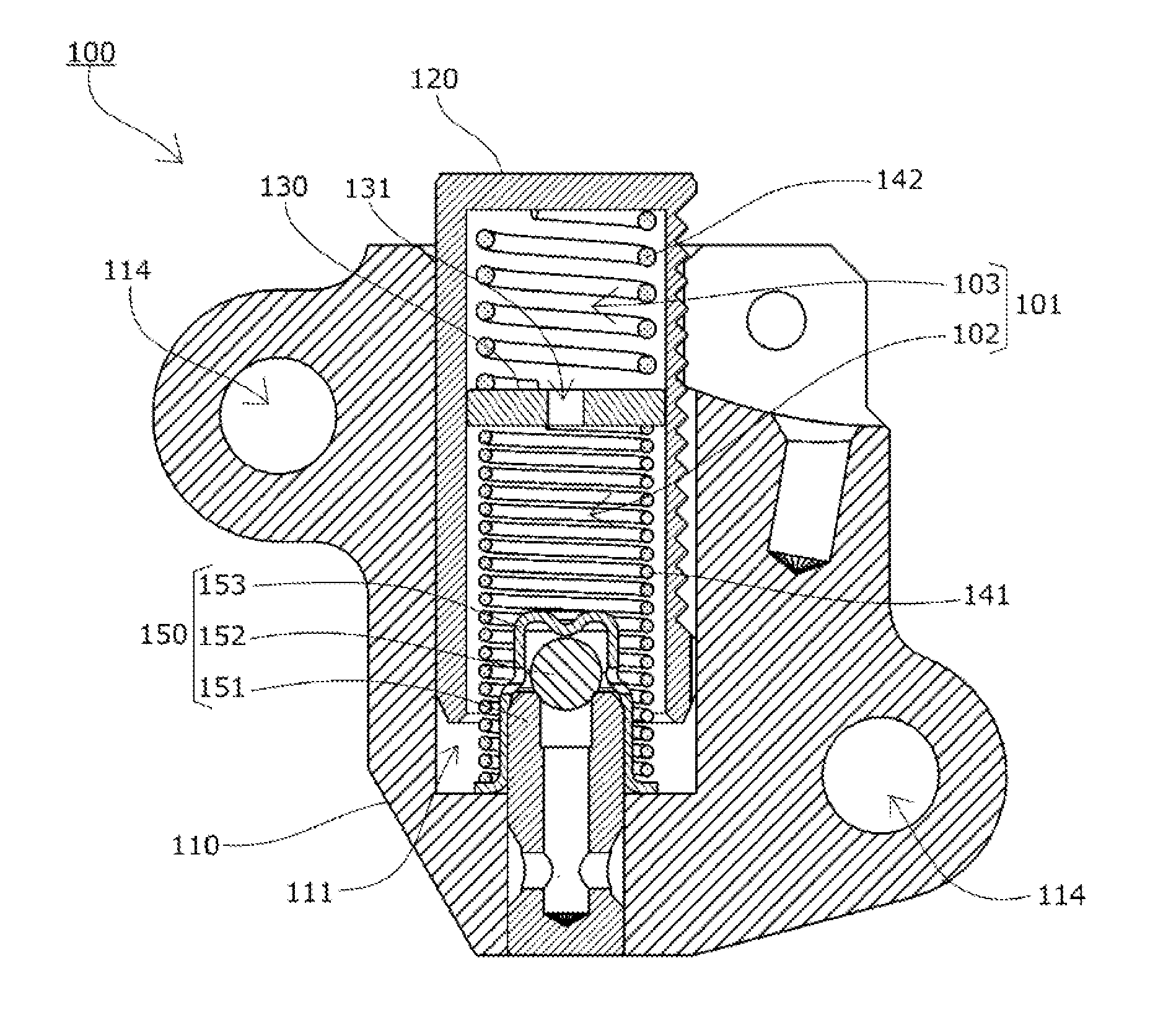
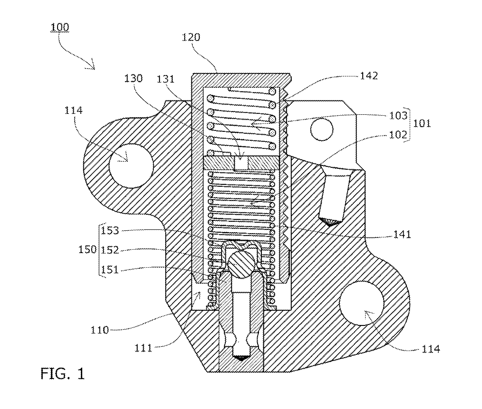
[0053]A chain tensioner 100 according to a first embodiment of the present invention will be described with reference to the drawings.

[0054]The chain tensioner 100 according to a first embodiment of the present invention includes, as shown in FIG. 1 to FIG. 3, a tensioner body 110 having a cylindrical plunger bore 111 with an open end, a cylindrical plunger 120 with a bottom, slidably inserted in the plunger bore 111, a first coil spring 141 and a second coil spring 142 that bias the plunger 120 in a protruding direction of the plunger 120, and a separator plate 130.

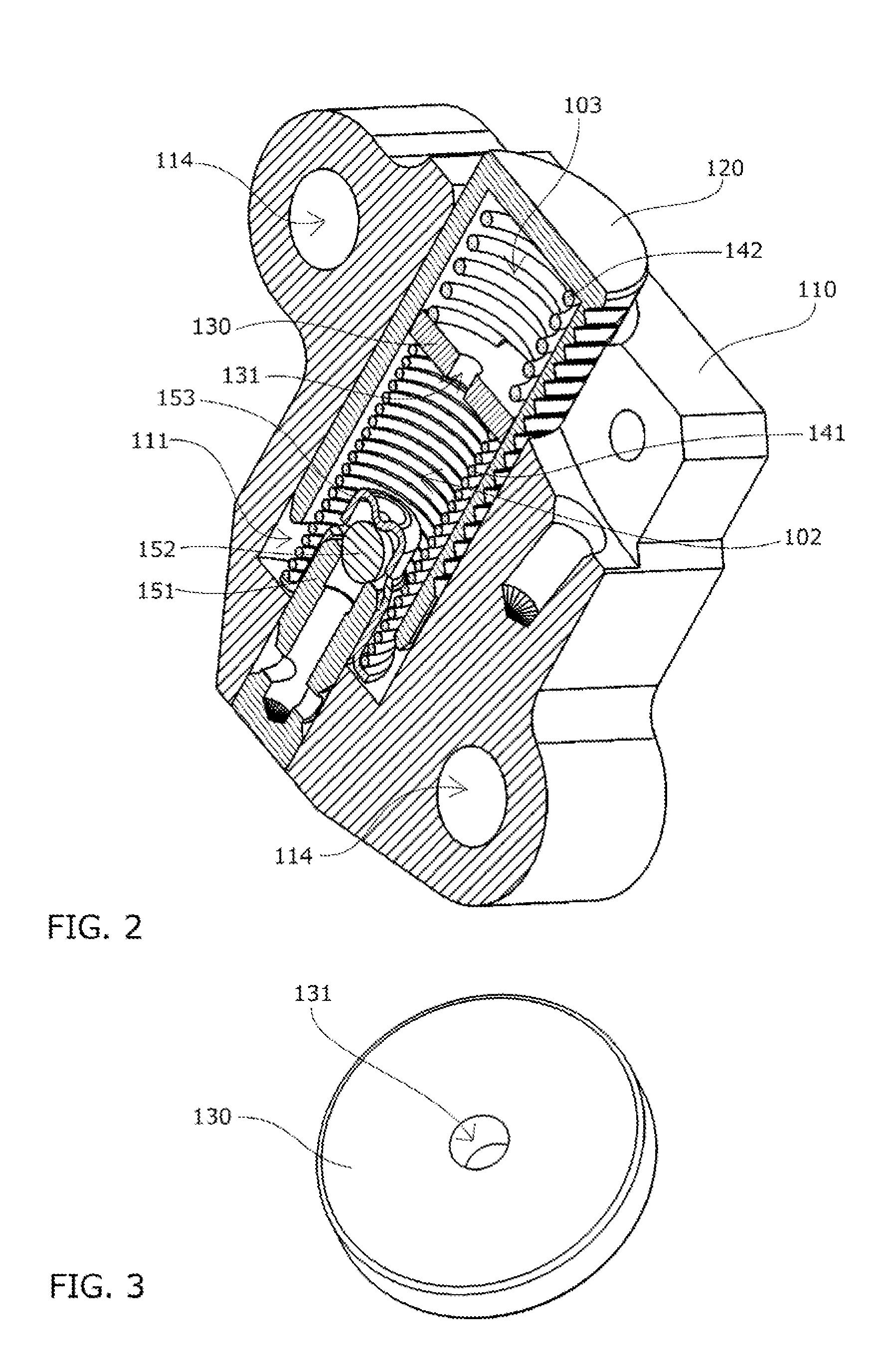
[0055]The first coil spring 141, separator plate 130, and second coil spring 142 are accommodated in series in a high pressure chamber 101 formed to extend over interiors of the plunger bore 111 and the plunger 120, the separator plate 130 partitioning the high pressure chamber 101 into a first high pressure chamber 102 and a second high pressure chamber 103.

[0056]The separator plate 130 has a through hole 131 that forms...

embodiment 2

[0088]The chain tensioner 100b according to a second embodiment of the present invention includes an additional separator plate 130 as well as a third coil spring 143 as compared to the chain tensioner 100 according to the previously described first embodiment, as shown in FIG. 12.

[0089]The first coil spring 141, separator plate 130, second coil spring 142, separator plate 130, and third coil spring are accommodated in series in a high pressure chamber 101 formed to extend over interiors of the plunger bore 111 and the plunger 120. The two separator plates 130 partition the high pressure chamber 101 into three compartments, i.e., a first high pressure chamber 102, a second high pressure chamber 103, and a third high pressure chamber 104.

[0090]The chain tensioner is configured the same in other respects as the chain tensioner 100 according to the first embodiment (same components and structures are given the same reference numerals as those of the first embodiment).

[0091]In this embo...


PUM


Abstract

Provided is a chain tensioner that can always provide a suitable reaction force and damping force to various tension fluctuations of the chain, has a simple structure, is easy to produce, and also enables a reduction in the production cost. The chain tensioner 100 has a plunger 120 inserted in a plunger bore 111, and biasing means 140 for biasing the plunger in a protruding direction of the plunger. A plurality of biasing means 140 are accommodated so as to freely expand and contract inside a high pressure chamber 101 and arranged in series along the protruding direction of the plunger 120, with a separator plate 130 interposed therebetween. The separator plate 130 has one or more oil passages that adjust oil flow.

Description

BACKGROUND OF THE INVENTION[0001]1. Field of the Invention[0002]The present invention relates to a chain tensioner that includes a tensioner body having a cylindrical plunger bore with an open end, a cylindrical plunger with a bottom, slidably inserted in the plunger bore, and biasing means that biases the plunger in a protruding direction of the plunger and is accommodated so as to freely expand and contract inside a high pressure chamber formed to extend over interiors of the plunger bore and the plunger, the chain tensioner maintaining appropriate tension of a chain.[0003]2. Description of the Related Art[0004]It has been common practice to use a chain tensioner for maintaining appropriate tension of a chain. For example, a timing system has been known, which has an endless timing chain such as a roller chain passing over respective sprockets of a crankshaft and a cam shaft inside an engine room, and which uses a chain tensioner to bias a pivoting chain guide having a guide shoe ...

Claims


Application Information

Patent Timeline
IPC IPC(8): F16H7/08
CPCF16H2007/0812F16H7/08F16H7/0836F16H7/0848F16H2007/0806F16H2007/0859F16H2007/0814F02B67/06F16H7/0838F16H7/10
Inventor TAKAGI, YUDAISONODA, MASATOSHI
Owner TSUBAKIMOTO CHAIN CO
Why Eureka
Try Eureka