Method for triggering solenoid valve and evaluation and control unit

A solenoid valve and electromagnetic damping technology, applied in the direction of electromagnets, electrical components, engine components, etc., can solve the problems of switching noise valve seat or valve closing component wear, etc., to achieve the effect of improving stability

Active Publication Date: 2021-05-28
ROBERT BOSCH GMBH
View PDF7 Cites 0 Cited by
  • Summary
  • Abstract
  • Description
  • Claims
  • Application Information

AI Technical Summary

Problems solved by technology

This causes switching noise and wear of the valve seat or valve closing element

Method used


Image

  • Method for triggering solenoid valve and evaluation and control unit
  • Method for triggering solenoid valve and evaluation and control unit
  • Method for triggering solenoid valve and evaluation and control unit

Examples


Embodiment Construction

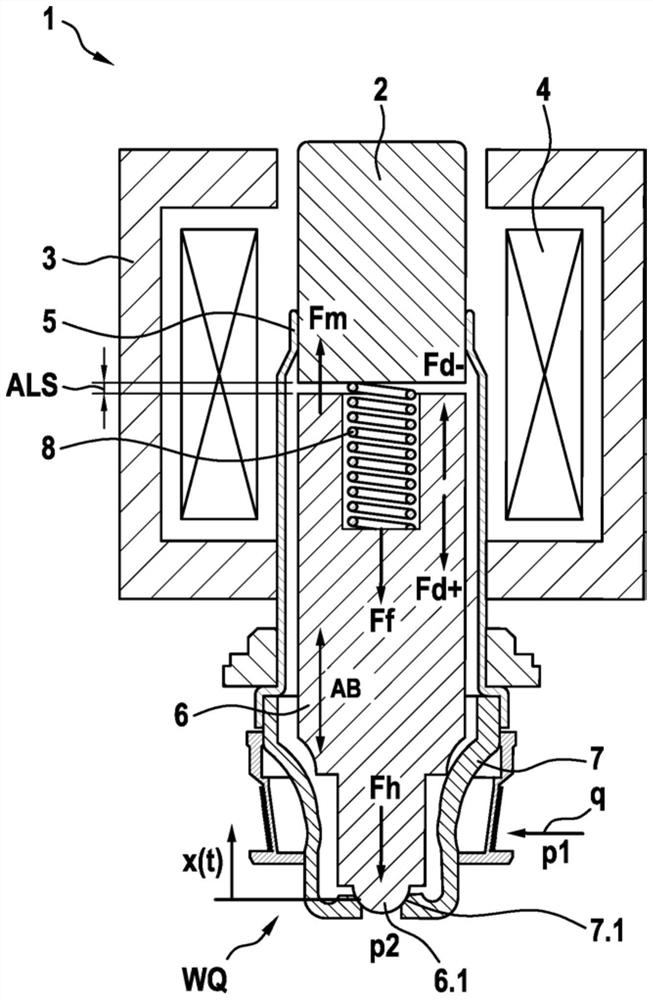
[0032] as by figure 1 It can be seen that the shown embodiment of the solenoid valve 1 comprises a magnet assembly 3 with an electric coil 4 and a movably supported magnet armature 6 with a closing element 6.1 which is activated by the magnet assembly 3 to overcome the return spring The force of 8 moves along the direction of motion. In the closed state of the solenoid valve 1 shown, the closing element 6.1 bears sealingly against the valve seat 7.1. In the open state of the solenoid valve 1 , not shown, the closing element 6 . 1 lifts off the valve seat 1 and sets the effective opening cross section WQ of the solenoid valve 1 .

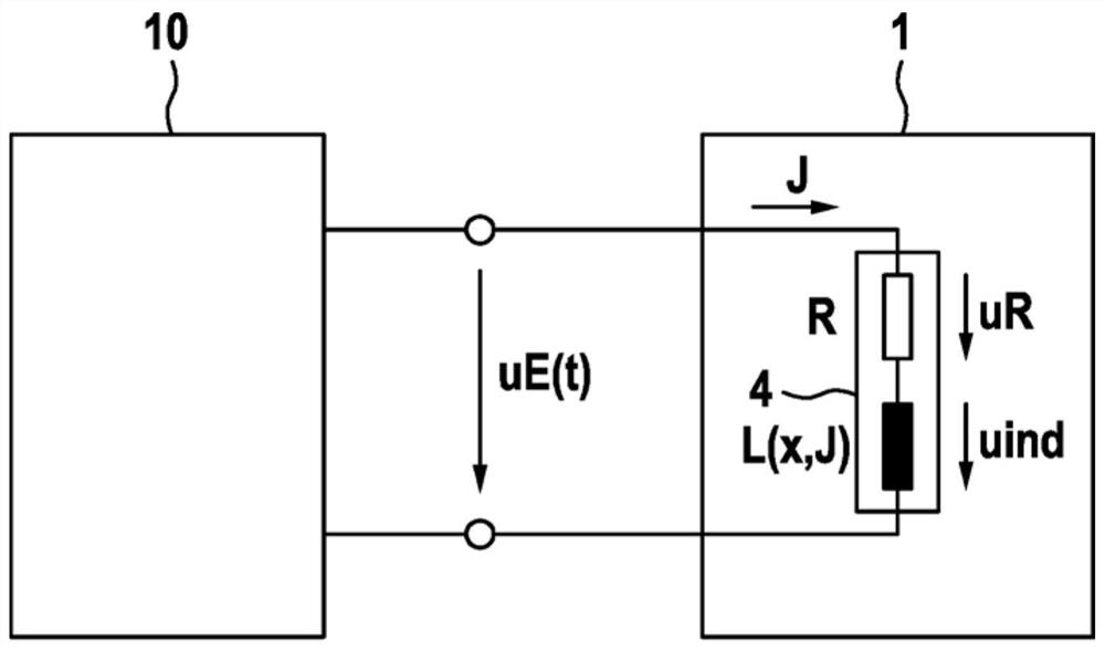
[0033] From figure 1 It can also be seen that the solenoid valve 1 shown corresponds to a normally closed 2 / 2 solenoid valve with the ball and cone seat in the closed armature position. From figure 2 It can also be seen that a voltage uE acts on the magnet assembly 3 , so that a coil current J flows in the electric coil 4 , whereby a magnetic fl...


PUM


Abstract

The invention relates to a method for triggering a solenoid valve. The solenoid valve includes a magnet assembly with an electric coil and a movably supported magnet armature with a closing element. The magnet armature is triggered by the magnet assembly to overcome force of a return spring to move in the direction of movement, wherein the closing element sealingly abuts against the valve seat in the closed state of the solenoid valve. When the solenoid valve is opened, the valve is lifted from the valve seat and adjusted the effective opening cross section of the solenoid valve. At least one input variable that affects or is affected by armature movement is detected. The armature stroke is estimated based on the detected at least one input variable. At least one electromagnetic damping variable used to affect the armature movement is calculated and outputted to the magnet assembly. At least one characteristic curve family or at least one mathematical function is used to estimate the armature stroke and calculate at least one electromagnetic damping variable.

Description

technical field [0001] The invention relates to a method for activating a solenoid valve and an evaluation and control unit for carrying out the method. Background technique [0002] For conventional vehicle braking systems, normally closed solenoid valves are usually used as switching valves in order to achieve different safety functions. Switching noise is generated when such a solenoid valve is opened or closed. The reason for the noise is that the armature of the solenoid valve hits the pole core (stop) of the valve at high speed when the valve is opened. When closing, the armature hits the valve seat with the closing element. This produces a large deceleration at the armature and thus a large time-dependent pulsating force in the valve. This leads to switching noise and wear to the valve seat or valve closing element. In principle, this factual situation also applies to other switching valves implementing the ABS or ESP safety functions. [0003] A method and a dev...

Claims


Application Information

Patent Timeline
Patent Type & Authority Applications(China)
IPC IPC(8): H01F7/18F16K31/06
CPCH01F7/18F16K31/0675F16K31/0696H01F2007/1894H01F7/1844H01F2007/185F16K31/0658
Inventor A·莱希勒G·施托克迈尔
Owner ROBERT BOSCH GMBH
Why Eureka
Try Eureka