A turn-over linkage damping mechanism for furniture

A technology of flipping linkage and damping mechanism, which is applied in the directions of building components, hinges with pins, and the arrangement of wings, can solve the problems of inability to meet the needs of use, inability to achieve uniformity, and large friction, and achieve fast adjustment and simple structure. Reasonable, small collision effect

Active Publication Date: 2017-10-13
伍志勇
View PDF1 Cites 0 Cited by
  • Summary
  • Abstract
  • Description
  • Claims
  • Application Information

AI Technical Summary

Problems solved by technology

It is said that this structure can reduce noise, and the closing or opening movement of the cabinet door is more flexible. During the movement of the cabinet door, the overall translational movement can avoid the situation that ordinary cabinet doors may hit the head; however, the upper The flap hinges only use the elastic device to achieve buffering and damping, and the force during the closing movement or opening movement cannot achieve a uniform effect, and the elastic device has a large friction force and high noise when the upper flap is hinged to open and close, which cannot meet the needs of users.

Method used


Image

  • A turn-over linkage damping mechanism for furniture
  • A turn-over linkage damping mechanism for furniture
  • A turn-over linkage damping mechanism for furniture

Examples


no. 1 example

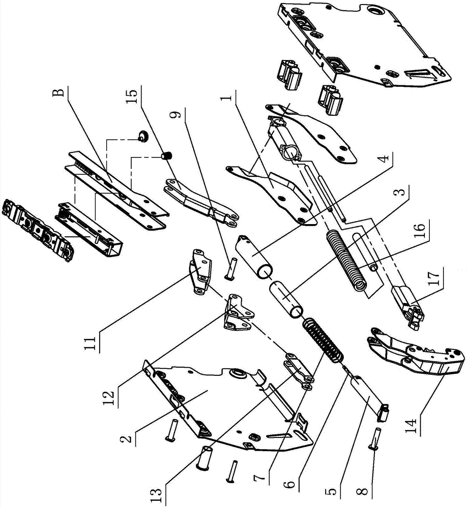
[0026] see Figure 1-Figure 6 , the flip linkage damping mechanism for furniture, including a push element 1, a connecting arm assembly and a fixed element 2, the push element 1 is hinged to the fixed element 2 through the connecting arm assembly, the fixed element 2 is provided with an elastic device, the push element 1 On the fixed element 2, a linkage damping device A is arranged between the pushing element 1 and the fixing element 2 through an elastic device, which at least includes a damper, a guide set 3 and a positioning set 4, and the damper includes Cylinder 5 and piston rod 6, one end of piston rod 6 extends into cylinder 5, the other end slides and expands outside cylinder 5, one end of guide set 3 is at least sleeved at one end of slide cylinder 5, and the other end of guide set 3 is sleeved to extend Out of the piston rod 6 outside the cylinder 5, one end of the positioning sleeve 4 is sleeved on the guide sleeve 3 and / or the cylinder 5, and the other end is posit...

no. 2 example

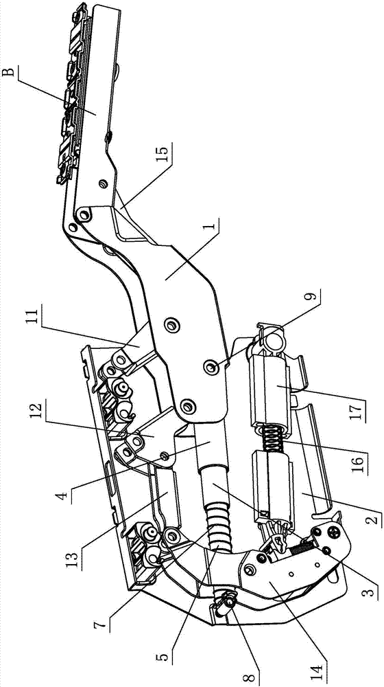
[0036] see Figure 7 , which is used for the flip linkage damping mechanism of furniture, which is different from the first embodiment in that: one end of the cylinder body 5 is positioned and rotated on the fixed element 2 through the first pin shaft 8, and one end of the piston rod 6 extends into the cylinder body 5 , the other end slides and expands outside the cylinder body 5, one end of the guide sleeve 3 is sleeved on the other end of the cylinder body 5, and the other end of the guide sleeve 3 is sleeved on the piston rod 6 extending out of the cylinder body 5, and is connected with the piston rod 6 extending outside the cylinder body 5. The ends of the piston rod 6 are matched and connected, one end of the positioning sleeve 4 is sleeved on the guide sleeve 3, and the other end is positioned and rotated on the pushing element 1 through the second pin shaft 9, and one end of the spring 7 elastically acts on the cylinder 5, and the other end elastically Acts on the pisto...

no. 3 example

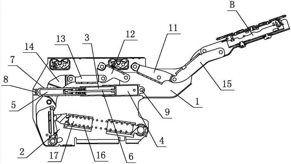
[0039] see Figure 8 , the flip linkage damping mechanism used for furniture is different from the first embodiment in that: one end of the piston rod 6 extends into the cylinder body 5, the other end slides and expands outside the cylinder body 5, and one end of the guide sleeve 3 passes through the third The pin shaft 10 is positioned and rotated on the fixed element 2, and is sleeved on the piston rod 6 extending out of the cylinder body 5, and is connected with the end of the piston rod 6 extending out of the cylinder body 5, and the other end of the guide sleeve 3 is sleeved on the cylinder One end of the body 5, one end of the positioning kit 4 is sleeved on the other end of the cylinder body 5, the other end of the positioning kit 4 is positioned and rotated on the pushing element 1 through the second pin shaft 9, one end of the spring 7 elastically acts on the cylinder body 5, and the other end elastically acts on the cylinder body 5 On guide kit 3.

[0040] Other unm...


PUM


Abstract

The invention relates to an overturning linkage damping mechanism used for furniture. The overturning linkage damping mechanism comprises an advancing element, a connecting arm component and a fixing element, wherein the advancing element is mutually hinged with the fixing element by virtue of the connecting arm component, an elastic device is arranged on the fixing element; the advancing element is elastically overturned, opened and closed on the fixing element by virtue of the elastic device; a linkage damping device is arranged between the advancing element and the fixing element; the linkage damping device at least comprises a damper, a guiding sleeve part and a locating sleeve part; the damper comprises a cylinder block and a piston rod; and when the advancing element is at least in an overturning closing stroke, the locating sleeve part locates and slides and drives the guiding sleeve part and the cylinder block to interact on each other, the length of the piston rod extending the cylinder block is gradually reduced, the damper is compressed, and buffering power is produced. By virtue of the improvement of the structure, the overturning linkage damping mechanism used for the furniture has the characteristics of simple and reasonable structure, safety and reliability, easiness in production and implementation, quickness in adjustment, easiness in operation, labour-saving and smooth starting and stopping process, small collision and low noise and is strong in practicability.

Description

technical field [0001] The invention relates to a flip linkage damping mechanism for furniture. Background technique [0002] The Chinese patent document number is CN202039710U, which discloses a hinge on November 16, 2011. The curved end of the first rotating arm of this structure is rotatably connected to the base plate, and the curved end of the second rotating arm is rotatably connected to the base plate. The two ends of the above-mentioned connecting arms that can overlap with the respective straight ends of the first rotating arm and the second rotating arm at the same time are rotatably connected with the respective straight ends of the first rotating arm and the second rotating arm respectively, and the connecting arms are located at the first Between the rotating arm and the second rotating arm, the bent end of the first rotating arm is hinged with the free end of the movable rod of the gas rod, and the fixed rod of the gas rod can be movably connected to the base p...

Claims


Application Information

Patent Timeline
Patent Type & Authority Patents(China)
IPC IPC(8): E05F3/20E05D3/14E06B3/38
CPCE05D3/14E05F3/20E06B3/385
Inventor 伍志勇
Owner 伍志勇
Why Eureka
Try Eureka