
Automobile magneto-rheological absorber based on multistage circumferential flow mode

A magnetorheological shock absorber, flow mode technology, applied in vibration suppression adjustment, non-rotation vibration suppression and other directions, can solve problems such as structural arrangement restrictions, achieve easy realization of component structure and shape, high magnetic field utilization, coil The effect of a small number of turns

Inactive Publication Date: 2015-06-10
袁显举
View PDF9 Cites 0 Cited by
  • Summary
  • Abstract
  • Description
  • Claims
  • Application Information

AI Technical Summary

Problems solved by technology

Many scholars at home and abroad have carried out research work in this area, such as multi-level coils, magnetic resistance rings, magnetic permeation rings, permanent magnets and other methods, but these methods are often limited by structural layout

Method used


Image

  • Automobile magneto-rheological absorber based on multistage circumferential flow mode
  • Automobile magneto-rheological absorber based on multistage circumferential flow mode
  • Automobile magneto-rheological absorber based on multistage circumferential flow mode

Examples


Embodiment Construction

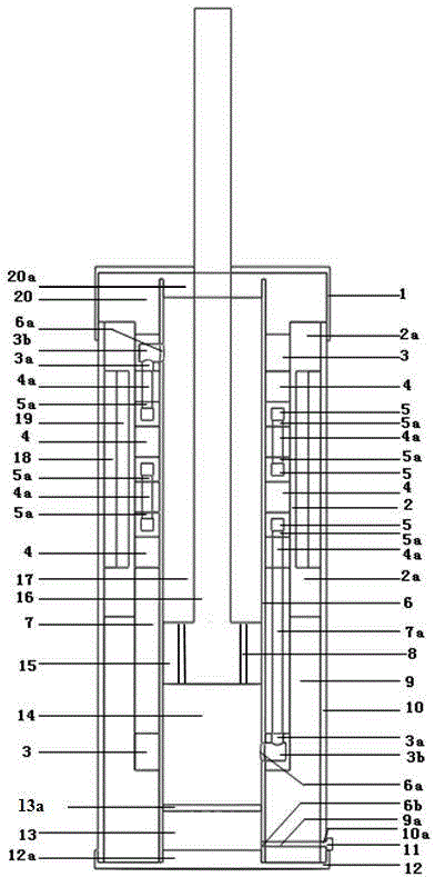
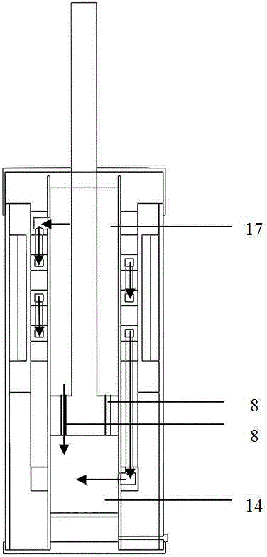
[0019] see figure 1 and figure 2 : The magneto-rheological shock absorber that the present invention relates to is made up of upper outer end cover 1, outer cylinder 2, outer cylinder end magnetic block 2a, circulation block 3, annular block 4 of high magnetic permeability, circumferential channel 5, Inner cylinder 6, support cylinder 7, support block 9, jacket 10, air nozzle 11, lower outer end cover 12, lower seal 12a, diaphragm 13a, piston 15, piston rod 16, magnetic guide cylinder 18, coil 19, upper Positioning cover 20, upper seal and guide 20a etc. are formed. Wherein: the coil 19 is wound on the outer wall of the outer cylinder 2, and the magnetic block 2a at the end of the outer cylinder itself is the main path of the magnetic circuit; The outer wall is co-located by the inner wall of the outer cylinder 2 in the radial direction, and is co-located by the flow cover 3, the support cylinder 7, and the support block 9 in the vertical direction; the inner cylinder 6 is ...


PUM


Abstract

The invention relates to an automobile magneto-rheological absorber based on a multistage circumferential flow mode. The absorber has an inner cylinder barrel which is packaged up and down. A piston having a certain number and aperture of piston holes and a piston rod are installed in the cylinder. The inner cylinder barrel has communication holes communicated with circumferential channels. Multistage circumferential channels are installed on the out wall of the inner cylinder barrel. Annular blocks with high magnetic conductive and the same sectional area as the circumferential channels are all arranged at both ends of each stage of the circumferential channel. The out wall of an external cylinder barrel is the winding position. Chucks themselves at the end of the external cylinder are main path of the magnetic force lines. A magnetic conductive cylinder is arranged between a coat of the absorber and a coil. The magnetic force lines form a closed loop circuit through the annular blocks, the circumferential channels and magnetorheological fluid, chucks at the end of the external cylinder, a magnetic conductive cylinder, and a support block upper end part. The maximum damping force provided by the structure is larger, the adjustment range is wider, the magnetic field use ratio is high, the energy consumption is little, the use is wide, the universality is strong, the structure is simple, it is convenient to maintain, and the absorber body has long service life.

Description

technical field [0001] The invention belongs to the configuration technical field of damping devices, and relates to a magneto-rheological shock absorber suitable for vehicle suspension systems. Background technique [0002] Common automotive magneto-rheological shock absorbers are mainly based on two modes: annular gap flow and pore flow in the cylinder. Limited by the structure of the traditional magneto-rheological shock absorber and the layout of the magnetic field, the proportion of the damping channel controlled by the magnetic field in these two modes is relatively small, the utilization rate of the magnetic field is low, and the range of the generated damping force is also limited. The structure can only be used for a specific car model, the structure itself does not have the ability to expand, nor can it be applied to more car models just by changing the magnetic field excitation current range. Improve the utilization rate of the magnetic field, try to ensure that ...

Claims


Application Information

Patent Timeline
Patent Type & Authority Patents(China)
IPC IPC(8): F16F9/53
Inventor 袁显举
Owner 袁显举
Learn More