
Disc type motor rotor disc vertical de-weight dynamic balancing method and equipment

A disc motor and balancing equipment technology, which is used in static/dynamic balance testing, machine/structural component testing, and measuring devices, etc., can solve the problem that the outer diameter of the disc motor rotor is large and the test device cannot meet the operational requirements. , easy to cause danger and other problems, to achieve the effect of eliminating the influence of shaft suction, convenient installation and detection, and convenient operation and installation

Active Publication Date: 2020-06-16
HANGZHOU ZONHOW ELECTRIC TECH CO LTD
View PDF6 Cites 0 Cited by
  • Summary
  • Abstract
  • Description
  • Claims
  • Application Information

AI Technical Summary

Problems solved by technology

Its shortcoming is that the outer diameter of the rotor disc of the disc motor is large and the axial dimension is small, and the test device cannot meet its operation requirements; at the same time, the magnetic steel on the rotor disc of the disc motor has a strong axial suction force, and the dynamic balance It is easy to cause danger and cause safety problems

Method used


Image

  • Disc type motor rotor disc vertical de-weight dynamic balancing method and equipment
  • Disc type motor rotor disc vertical de-weight dynamic balancing method and equipment
  • Disc type motor rotor disc vertical de-weight dynamic balancing method and equipment

Examples


Embodiment Construction

[0030] The present invention will be further described below in conjunction with the drawings and specific embodiments.

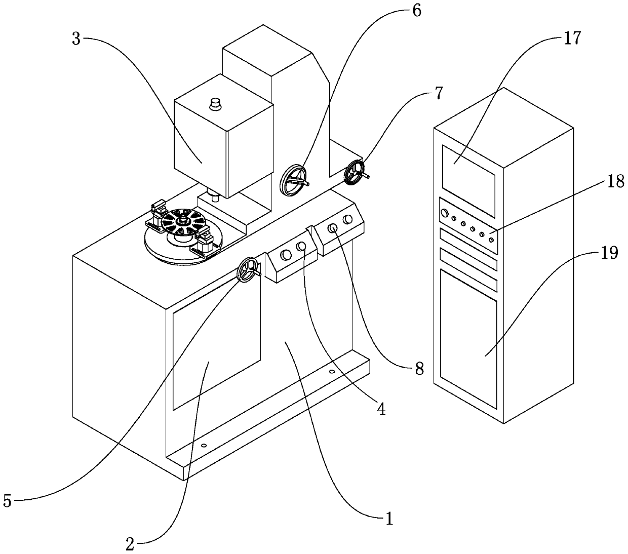
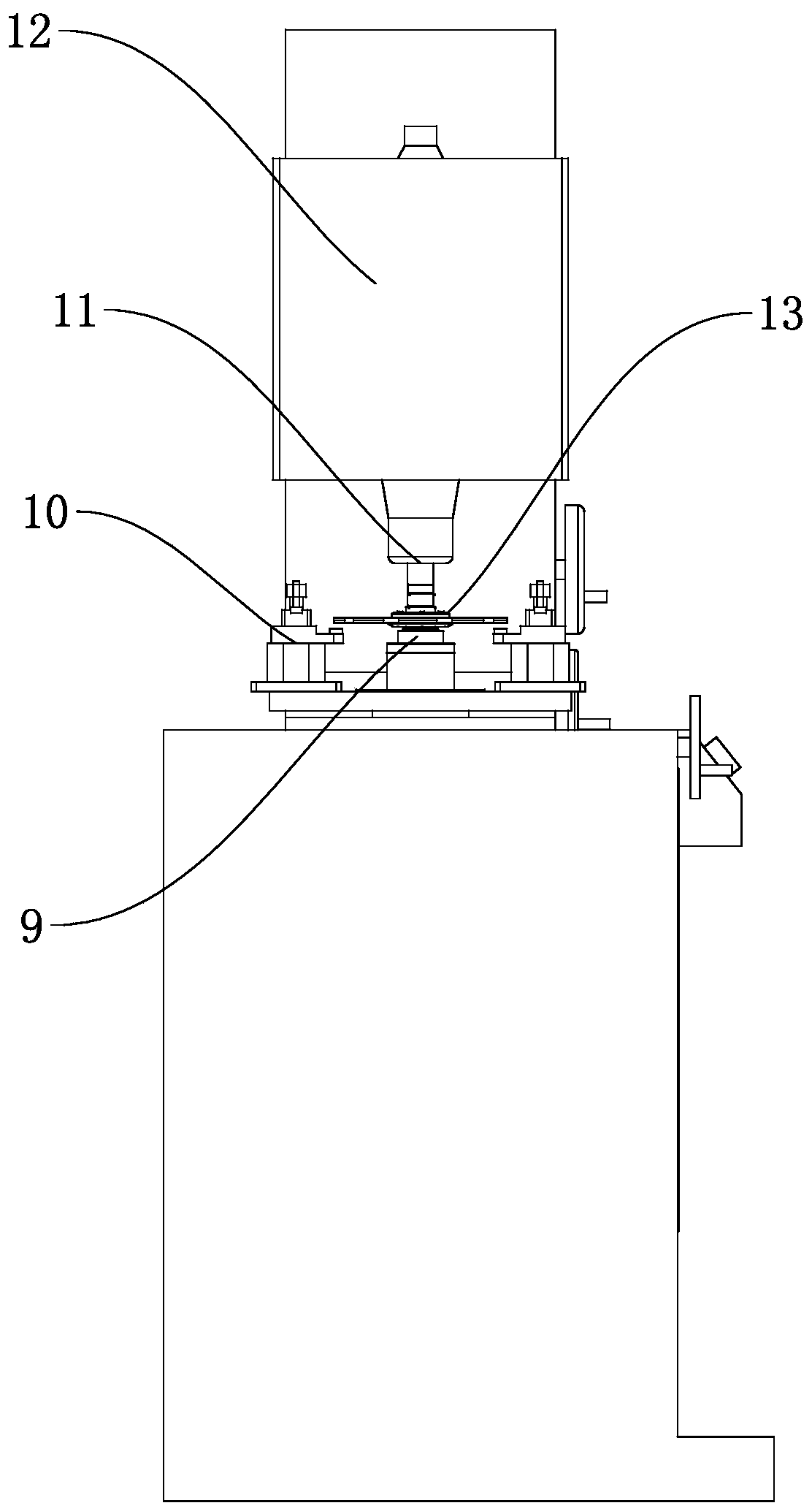
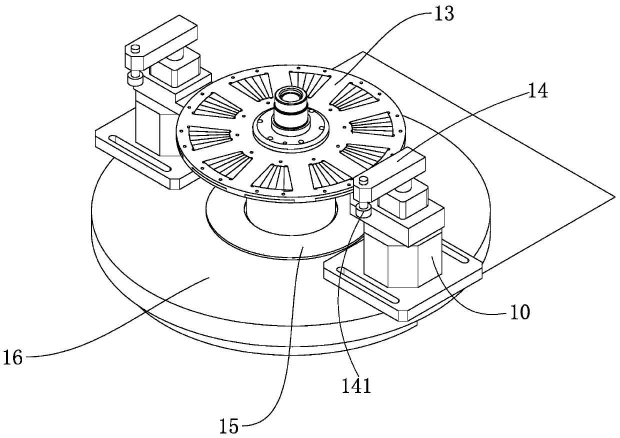
[0031] Such as Figure 1 to Figure 4 The illustrated embodiment is a vertical weight-removing dynamic balancing device for a disc motor rotor disc, which is characterized in that it includes a dynamic balancing machine body 1, which adopts the model PHLD-35H. The main body 1 of the dynamic balancing machine is equipped with an electric control box 19, and the electric control box 19 is provided with a control button 18 and a dynamic balance result display 17. The upper side of the dynamic balancing machine body 1 is provided with a rotatable rotating table 16, and the rotating table 16 is equipped with a rotating hand wheel 5. The body 1 of the dynamic balancing machine electrically drives the rotating table 16 to rotate through the traditional transmission mechanism 2, which is well known to those skilled in the art. In order to save space, the specific form...


PUM


Abstract

The invention discloses a disc type motor rotor disc vertical de-weight dynamic balancing method and disc type motor rotor disc vertical de-weight dynamic balancing equipment. The disc type motor rotor disc vertical de-weight dynamic balancing equipment comprises a dynamic balancing machine body, wherein the upper side of the dynamic balancing machine body is provided with a rotatable rotating table, the axis of the rotating table is vertically arranged, the rotating table is provided with a rotor clamp used for clamping a rotor disc to be measured, the rotor clamp is provided with an index plate, and the rotating table is further provided with a clamping device used for removing weight the rotor disc; and a de-weight device capable of moving relative to the rotary table is further arranged above the dynamic balancing machine body. The disc type motor rotor disc vertical de-weight dynamic balancing method and the disc type motor rotor disc vertical de-weight dynamic balancing equipmenthave the advantages that vertical dynamic balance measurement of the rotor disc is achieved, the rotor disc is convenient to install and detect and is evenly influenced by an axial suction force of rotor disc magnetic steel, the influence of the axial suction force of the magnetic steel on rotor disc dynamic balance measurement is eliminated, and the disc type motor rotor disc vertical de-weightdynamic balancing method and the disc type motor rotor disc vertical de-weight dynamic balancing equipment are stable in performance and high in precision compared with a traditional horizontal rotordynamic balance measuring machine; and through using the de-weight device, the de-weight of the rotor disc can be realized, so that the dynamic balance precision of the rotor disc is shared.

Description

Technical field [0001] The invention belongs to the technical field of disc motor rotor discs, in particular to a method and equipment for vertical weight reduction and dynamic balancing of disc motor rotor discs. Background technique [0002] For disc motor rotors due to manufacturing, processing, assembly errors and other reasons, the rotor is mechanically unbalanced. Due to the eccentric inertia during rotation, unbalanced centrifugal force or centrifugal force couples will be generated, which will cause the motor to vibrate under the action of centrifugal force. . Vibration is very harmful to the motor, it will consume energy, reduce the power of the motor, damage the bearing, accelerate wear and reduce the life, etc.; the special shape of the disc rotor disc, large outer diameter, small axial size, ordinary horizontal dynamic balance method can not It satisfies its job requirements very well. [0003] For example, Chinese patent document CN 208921350U disclosed "a rotor dyna...

Claims


Application Information

Patent Timeline
IPC IPC(8): G01M1/34
CPCG01M1/34
Inventor 徐鹏张国强陈栋李国瑶
Owner HANGZHOU ZONHOW ELECTRIC TECH CO LTD
Learn More