

Motion reduction apparatus and floating body therewith
a technology of motion reduction and apparatus, which is applied in the direction of foiling, vessel movement reduction, shipping equipment, etc., can solve the problems of insufficient for many purposes, and achieve the effect of reducing motion and high safety of operation
- Summary
- Abstract
- Description
- Claims
- Application Information
AI Technical Summary
Benefits of technology
Problems solved by technology
Method used
Image

Examples
first embodiment
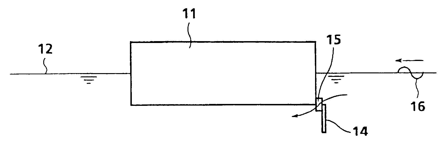
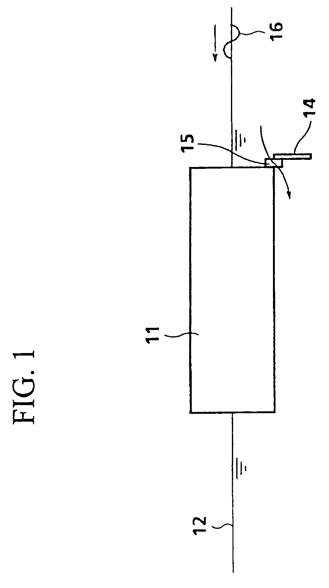
[0094]The floating body motion reduction apparatus in the first embodiment will be explained along with FIGS. 1 to 6. As shown in FIGS. 1 and 2, in the floating body motion reduction apparatus in this embodiment, the floating main body 11 is made with steel plates, for example, into an orthorhombic shaped structural body, and the interior space is made into a number of floating chambers (omitted from the diagram). The floating main body 11 is, therefore, able to float above the waterline 12 due to the lifting force generated by the floating chambers.
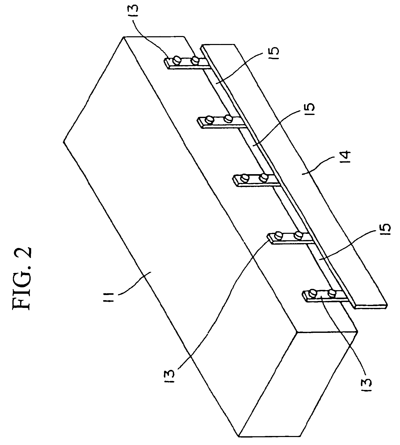
[0095]On one lateral side in the longitudinal direction of the floating main body 11, i.e., the side surface, a plumb plate 14 is supported on the side surface separated at a distance from the floating main body 11, by means of a plurality of stay plates 13 at approximately in the vertical direction. The plumb plate 14 is made of a flat plate and has essentially the same longitudinal dimension as the floating main body 11, and the upper ...
third embodiment
[0108]FIG. 11 shows the motion reduction apparatus. As shown in FIG. 11, the floating main body 31 in this motion reduction apparatus is constructed substantially the same as the floating main body 11 or 21 in the preceding embodiments, but the longitudinal lateral surface, i.e., the side surface supports a freely pivoting swing plate 34 at a given distance away from the floating main body 31 by way of a plurality of brackets 33. The swing plate 34 can swing by operating a drive device (not shown), and is able to be positioned in three positions: (1) a retreat position situated above the bottom surface of the floating main body 31 (solid line in FIG. 11); (2) a horizontal position at about the same level as the bottom surface of the floating main body 31 (double-dot?? single-dot line in FIG. 11); and (3) a plumb position extending beyond the bottom surface of the floating main body 31 (single-dot line in FIG. 11). Also, water is able to flood through the flow sections 35 formed betw...
fourth embodiment
[0114]the motion reduction apparatus will be explained along with FIGS. 13 and 14. The motion reduction apparatus in this embodiment has a floating main body 41 of a similar structure to the floating main body 11, 21, or 31 provided with a water surface plate 44 fixed to the front end and back end sections parallel to the water surface in the longitudinal direction.
[0115]When the floating main body 41 having such a water surface plate 44 floating on the water is impacted (right side in FIG. 13) by the incoming waves 16, the incoming waves 16 hit the front plane of the floating main body 41, but the water surface plate 44 provides resistance to suppress pitching of the floating main body 41, thus reducing motion of the floating main body 41.
[0116]FIG. 14 shows a graph of comparison of wave period and pitching amplitude of the floating main body in the cases of: (1) floating main body by itself; (2) affixing the water surface plate 44 on either the front end section or the back end se...
PUM
 Abstract
Description
Claims
Application Information