Expandable arrow broadhead with cutting blade locking notch

a technology of expanding arrows and broadheads, which is applied in the field of expanding arrow broadheads, can solve the problems that none of the above mentioned prior art broadhead patents particularly discloses or instructs, and achieves the effects of quick and humane killing, increased hemorrhage, and large cutting diameter

Active Publication Date: 2010-03-16
BEAR ARCHERY
View PDF13 Cites 14 Cited by
  • Summary
  • Abstract
  • Description
  • Claims
  • Application Information

AI Technical Summary

Benefits of technology

[0008]Another object of the arrow broadhead is the expanded blades, held in a locked position, provide for a large cutting diameter to cause increased hemoraging and a quick and more humane kill when hunting deer, elk and other animals. The locked blades insure that the blades are held in place in an extended position for cutting a large opening in the target.

Problems solved by technology

None of the above mentioned prior art broadhead patents particularly disclose or teach the structure and function of an arrow broadhead having a sliding shaft with pointed tip and cutting blades attached.

Method used


Image

  • Expandable arrow broadhead with cutting blade locking notch
  • Expandable arrow broadhead with cutting blade locking notch
  • Expandable arrow broadhead with cutting blade locking notch

Examples


Embodiment Construction

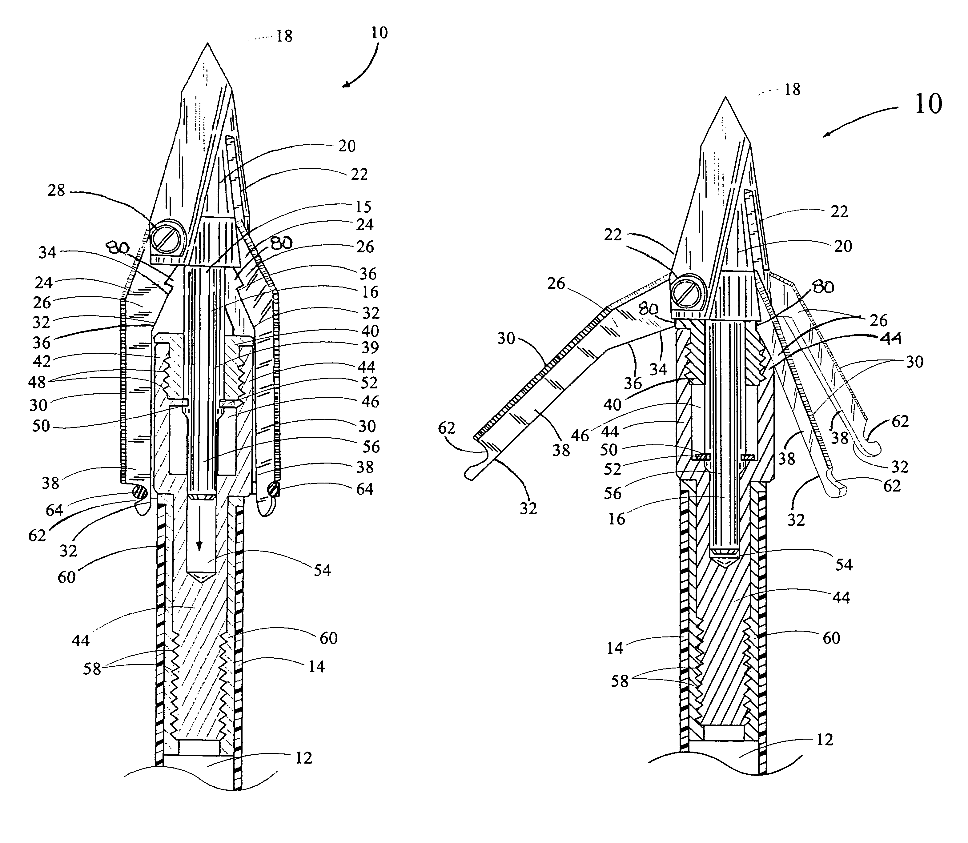
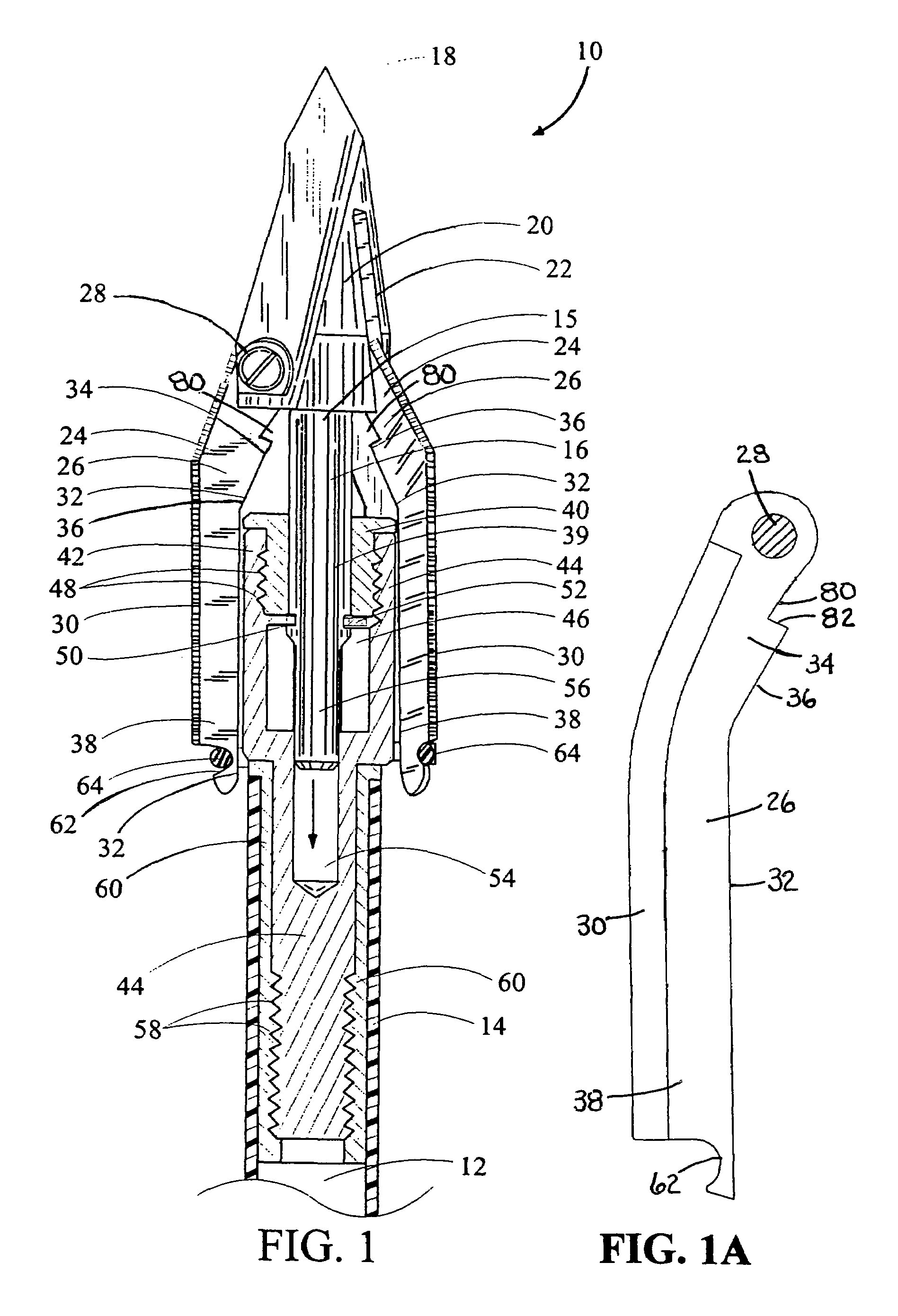
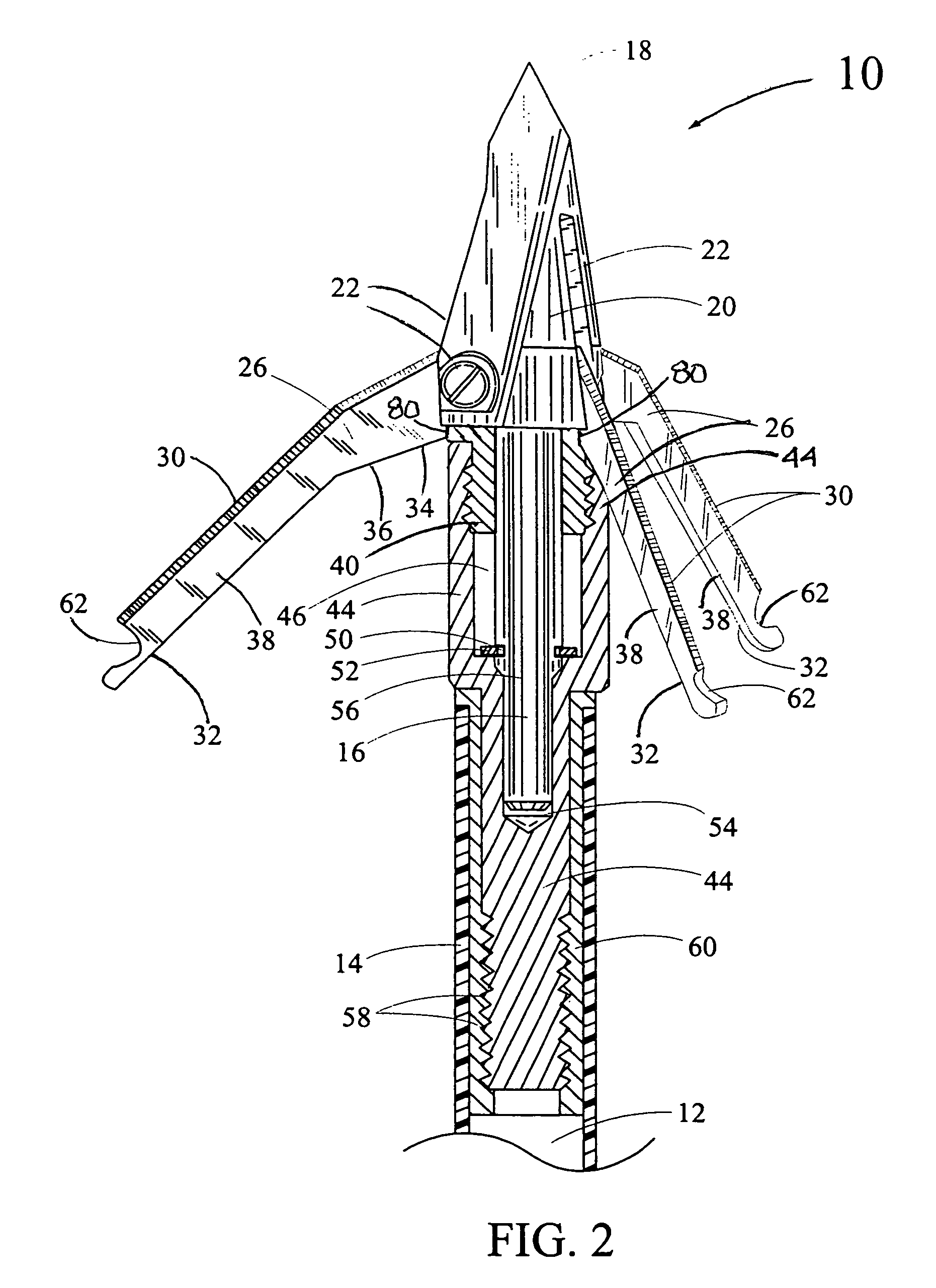
[0020]In FIG. 1, a side view of a primary embodiment of the subject arrow broadhead is shown and having general reference numeral 10. The arrow broadhead 10 is adapted from mounting to an open end 12 of a hollow arrow shaft 14. A portion of the arrow shaft 14 is shown in cross section.

[0021]The arrow broadhead 10 includes a sliding shaft 16 with a pointed tip 18 formed in a front portion 15 of the shaft 16. The pointed tip 18 is tapered rearwardly and outwardly forming a tip base 20. The tip base 20 includes grooves 22 formed therein and parallel to a length of the sliding shaft 16. The grooves 22 are used for receiving a pivot end 24 of two or more of cutting blades 26 equally spaced around the circumference of the tip base 20. In this drawing, two of the cutting blades 26 can be seen. In FIG. 5, three of the cutting blades 26 are shown and equally spaced around the tip base 20. The pivot end 24 of the cutting blades 26 is attached to the sides of the grooves 22 using pivot pins 28...


PUM


Abstract

An expandable arrow broadhead used for releasable attachment to one end of a hollow arrow shaft. The broadhead includes a sliding shaft with a pointed tip and tip base having two or more of cutting blades mounted thereon. Each of the blades includes an outer cutting edge and an inner edge with a beveled cam surface and locking notch therein. A portion of the sliding shaft is slidably received inside a hollow collar. The collar is attached to a sliding shaft housing. The sliding shaft housing is attached to an arrow shaft insert. The arrow shaft insert is adapted for receipt inside one end of the arrow shaft. In a retracted position, the blades are disposed next to and parallel to the length of the sliding shaft. When the pointed tip engages a target, the sliding shaft moves inwardly and rearwardly sliding inside the collar and inside a sliding shaft bore hole in the sliding shaft housing. As the sliding shaft moves rearwardly, the beveled cam surface of the blades engages a portion of the collar, which moves the blades outwardly with locking notch securing the blades in an extended position.

Description

[0001]This application is a Continuation-In-Part patent application of an application filed on Apr. 24, 2006, Ser. No. 11 / 410,771 now U.S. Pat. No. 7,226,375, by the subject inventor and having a title of “EXPANDABLE ARROW BROADHEAD FOR ATTACHMENT TO ONE END OF AN ARROW SHAFT.BACKGROUND OF THE INVENTION[0002](a) Field of the Invention[0003]This invention relates broadly to an expandable arrow broadhead and more particularly, but not by way of limitation, to an arrow broadhead having a sliding shaft for extending outwardly at least two cutting blades upon impact on a target. The cutting blades include a locking notch formed therein for holding the blades in an open, extended position when contacting the target.[0004](b) Discussion of Prior Art[0005]Heretofore, there have been a number of arrow broadheads having blades that extend outwardly when contacting a surface of a target. U.S. Pat. No. 6,935,976 to Grace, Jr. et al., discloses a mechanical broadhead having blades, mounted in lo...

Claims


Application Information

Patent Timeline
Patent Type & Authority Patents(United States)
IPC IPC(8): F42B6/08
CPCF42B6/08
Inventor SANFORD, CHRIS
Owner BEAR ARCHERY
Why Eureka
Try Eureka