Anti-drool mechanism for a sprue bushing

a technology of anti-drool and sprue bushing, which is applied in the field of injection molding apparatus, can solve the problems of increased production costs, molten material leakage, and adversely affecting the next melt shot, so as to reduce the production cost, and avoid the effect of drool

Active Publication Date: 2010-03-16
MOLD MASTERS 2007
View PDF23 Cites 4 Cited by
  • Summary
  • Abstract
  • Description
  • Claims
  • Application Information

AI Technical Summary

Benefits of technology

[0006]According to an embodiment of the present invention there is provided an injection molding apparatus which has a sprue bushing with a melt channel for receiving a melt stream of moldable material under pressure. The sprue bushing melt channel has a shut-off valve to prevent melt from drooling between injection cycles.

Problems solved by technology

In the event that the machine nozzle has to be disengaged from making contact with the sprue bushing, molten plastic will drool backwards from the sprue bushing, and this will adversely affect the next shot of melt.
Due to residual pressures in the system, molten material tends to leak, or “drool”, from the sprue bushing at the end of the injection cycle, i.e., when the machine nozzle is retracted from the sprue bushing inlet.
This drool represents waste material and increased production costs.
Further, the drooled material may collect on the mold and prevent complete closing thereof or cause permanent damage thereto.

Method used


Image

  • Anti-drool mechanism for a sprue bushing
  • Anti-drool mechanism for a sprue bushing
  • Anti-drool mechanism for a sprue bushing

Examples


Embodiment Construction

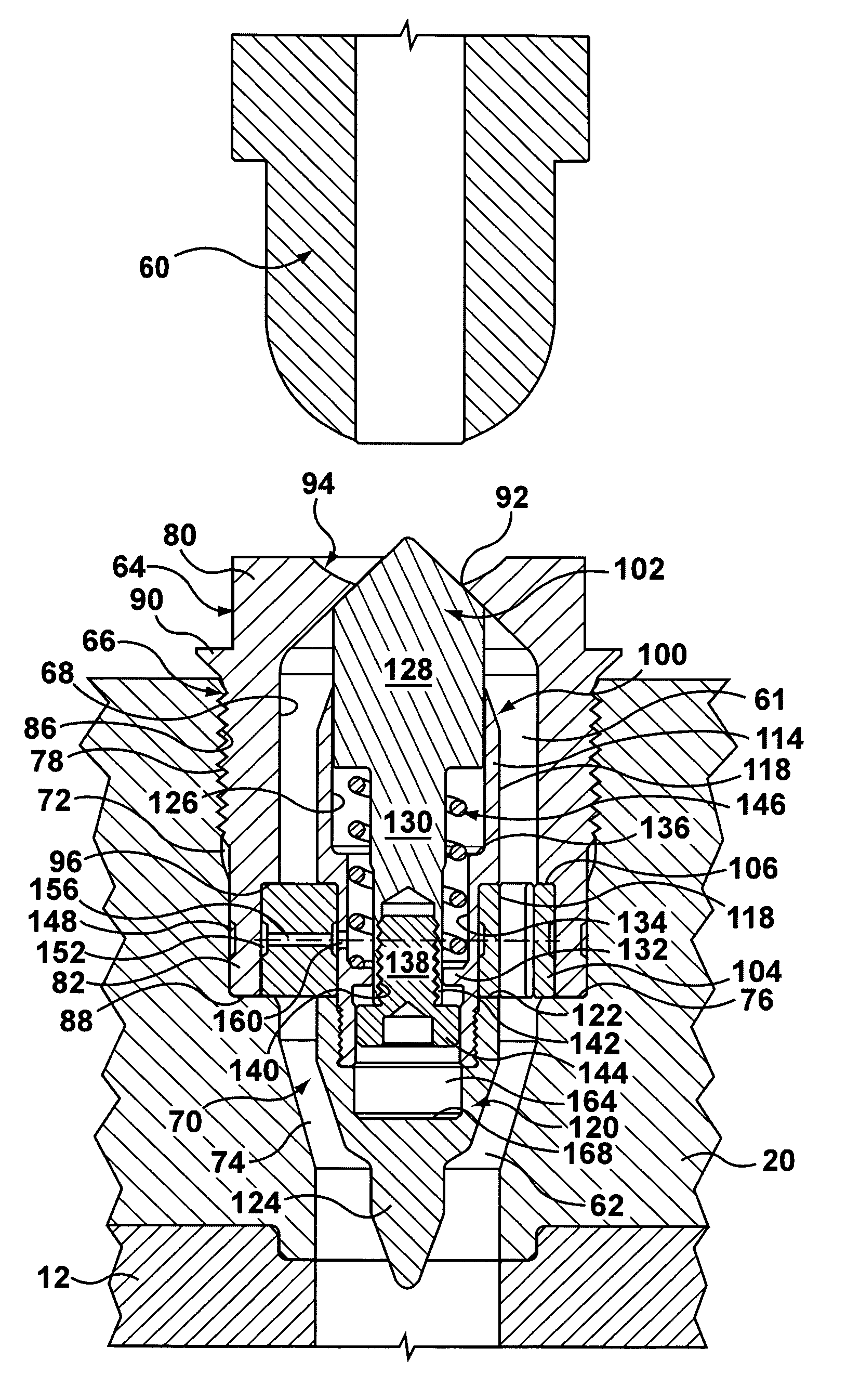
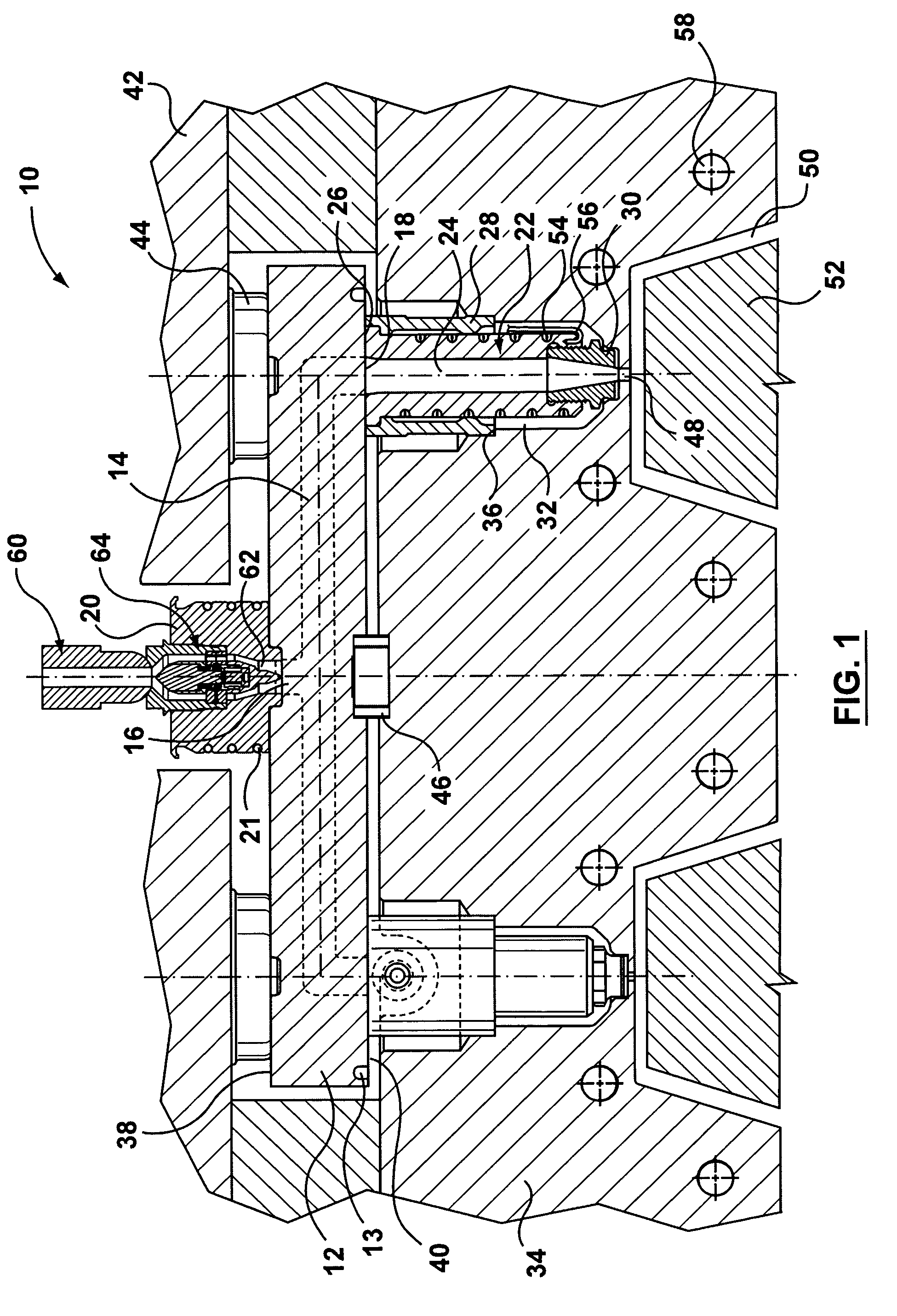
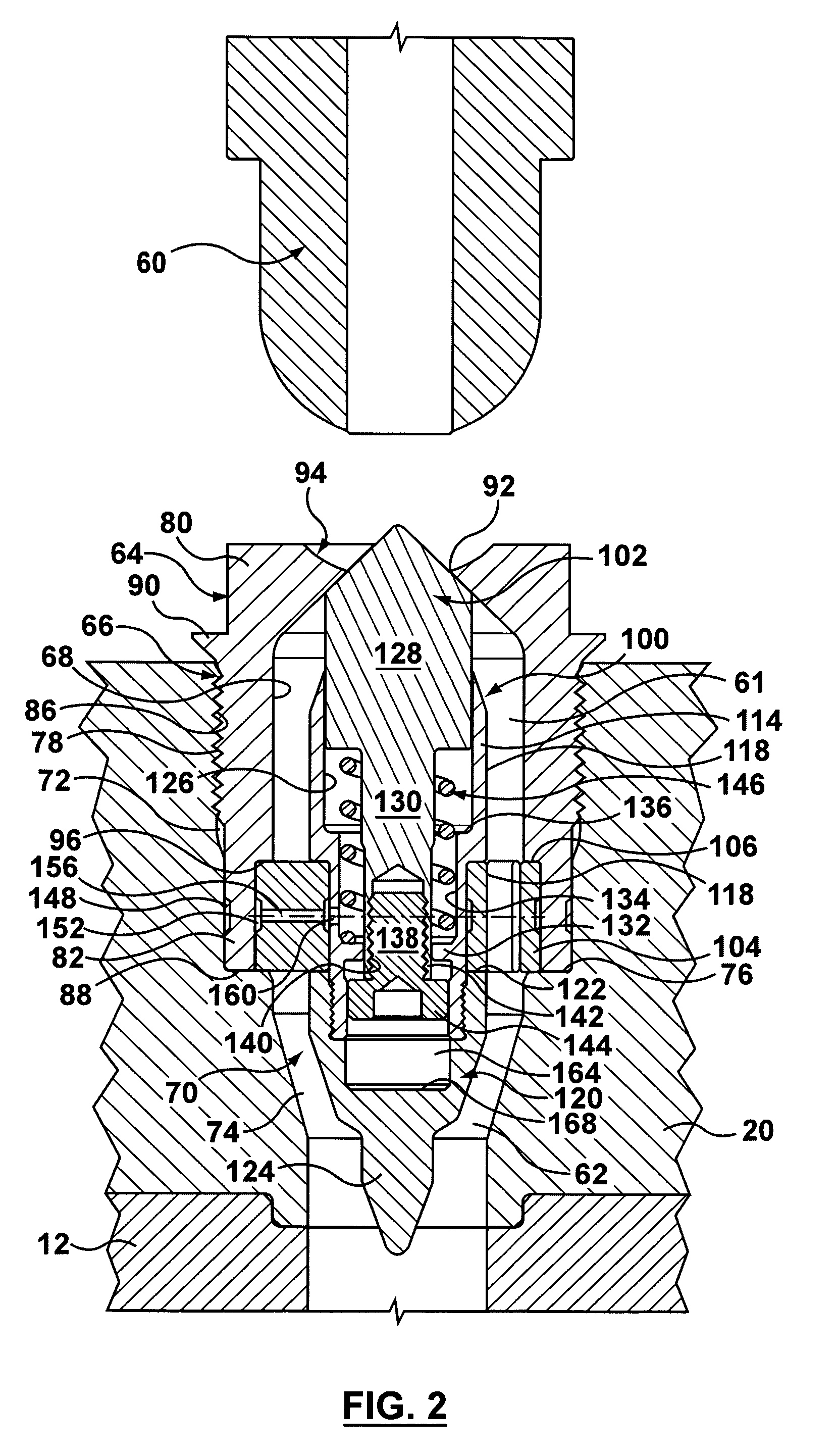
[0015]Referring now to FIG. 1, an injection molding apparatus 10 is generally shown. Injection molding apparatus 10 includes a manifold 12 having a manifold melt channel 14. Manifold melt channel 14 extends from an inlet 16 to manifold outlets 18. Inlet 16 of manifold melt channel 14 receives a melt stream of moldable material from a machine nozzle 60 through melt channel 62 of a sprue bushing 20 and delivers the melt to hot runner nozzles 22, which are in fluid communication with respective manifold outlets 18. Sprue bushing 20 is heated by heater 21 and manifold 12 is heated by heater 13. The sprue bushing 20 includes a shut-off valve 64, which will be described below. The shut-off valve is generally an anti-drool mechanism for reducing the occurrence of drool when the machine nozzle 60 is de-coupled from the sprue bushing 20.

[0016]Although a pair of hot runner nozzles 22 is shown in FIG. 1, it will be appreciated that a typical injection molding apparatus may include only one or ...


PUM

PropertyMeasurementUnit
pressureaaaaaaaaaa
meltaaaaaaaaaa
residual pressuresaaaaaaaaaa

Abstract

A shut-off valve for preventing drool from an injection molding apparatus is provided in a melt channel of a sprue bushing. The shut-off valve includes a fixed member located in the melt channel and a reciprocating member coupled to the fixed member. The reciprocating member is biased toward an extended position in which an inlet of the sprue bushing is blocked thereby. The reciprocating member is movable from the extended position towards a retracted position in which the inlet of the sprue bushing is clear by the force of a melt stream entering the melt channel of the sprue bushing.

Description

FIELD OF THE INVENTION[0001]The present invention relates generally to an injection molding apparatus and, in particular to an anti-drool mechanism for a sprue bushing.BACKGROUND OF THE INVENTION[0002]Many injection molding systems use a sprue bushing to provide a transfer melt channel between the machine nozzle and a distribution manifold in a mold. In the event that the machine nozzle has to be disengaged from making contact with the sprue bushing, molten plastic will drool backwards from the sprue bushing, and this will adversely affect the next shot of melt. This situation can happen in many applications, such as for example with shuttle molds, rotary molds, and stack molds.[0003]Due to residual pressures in the system, molten material tends to leak, or “drool”, from the sprue bushing at the end of the injection cycle, i.e., when the machine nozzle is retracted from the sprue bushing inlet. This drool represents waste material and increased production costs. Further, the drooled...

Claims


Application Information

Patent Timeline
Patent Type & Authority Patents(United States)
IPC IPC(8): B29C45/38
CPCB29C45/234B29C45/322
Inventor KLOBUCAR, PETER
Owner MOLD MASTERS 2007
Why Eureka
Try Eureka