
Pipette-Fillable Cartridge

a cartridge and pipette technology, applied in the field of chemical or biological assays, can solve the problems of inability to use a completely prefilled cartridge in the life science field, inkjet printing, and time-consuming procedures

Active Publication Date: 2022-07-21
FUNAI ELECTRIC CO LTD
View PDF4 Cites 0 Cited by
  • Summary
  • Abstract
  • Description
  • Claims
  • Application Information

AI Technical Summary

Benefits of technology

The patent text describes a method to use standard inkjet printers for life-sciences applications by modifying the printhead reservoir bodies to allow for easy refueling and maintaining the form factors of standard printers. The method also includes the use of pressure compensation to prevent fluid drooling and allow for efficient use of the fluid chamber. Additionally, a single fluid ejection head chip is attached to the cartridge for multiple fluid reservoirs to improve positional accuracy of fluid droplets. The technical effects of this patent include reducing sample waste and cost by using pre-existing inkjet printers, improving positional accuracy of fluid droplets, and increasing throughput of assay samples.

Problems solved by technology

When there are a large number of patients that require blood sample analysis, the procedures may be extremely time consuming.
Due to the small-scale volumetric limitations of pipettes, it is often necessary to create an excess of testing fluid to achieve the proper ratio of reagents.
However, it is impractical to use a totally prefilled cartridge in the life-sciences field where it is desirable to produce testing solutions on site.
While inkjet printing may be a viable method of administering chemical and biological assay analysis, inkjet printing products currently on the market use specialty printers and specially designed printheads which are cost prohibitive to some researchers.
Without backpressure control of the fluid in the reservoir, ejection heads are quite limited to the volume of liquid that can be contained in the fluid reservoir without experiencing drooling.

Method used


Image

  • Pipette-Fillable Cartridge
  • Pipette-Fillable Cartridge
  • Pipette-Fillable Cartridge

Examples


Embodiment Construction

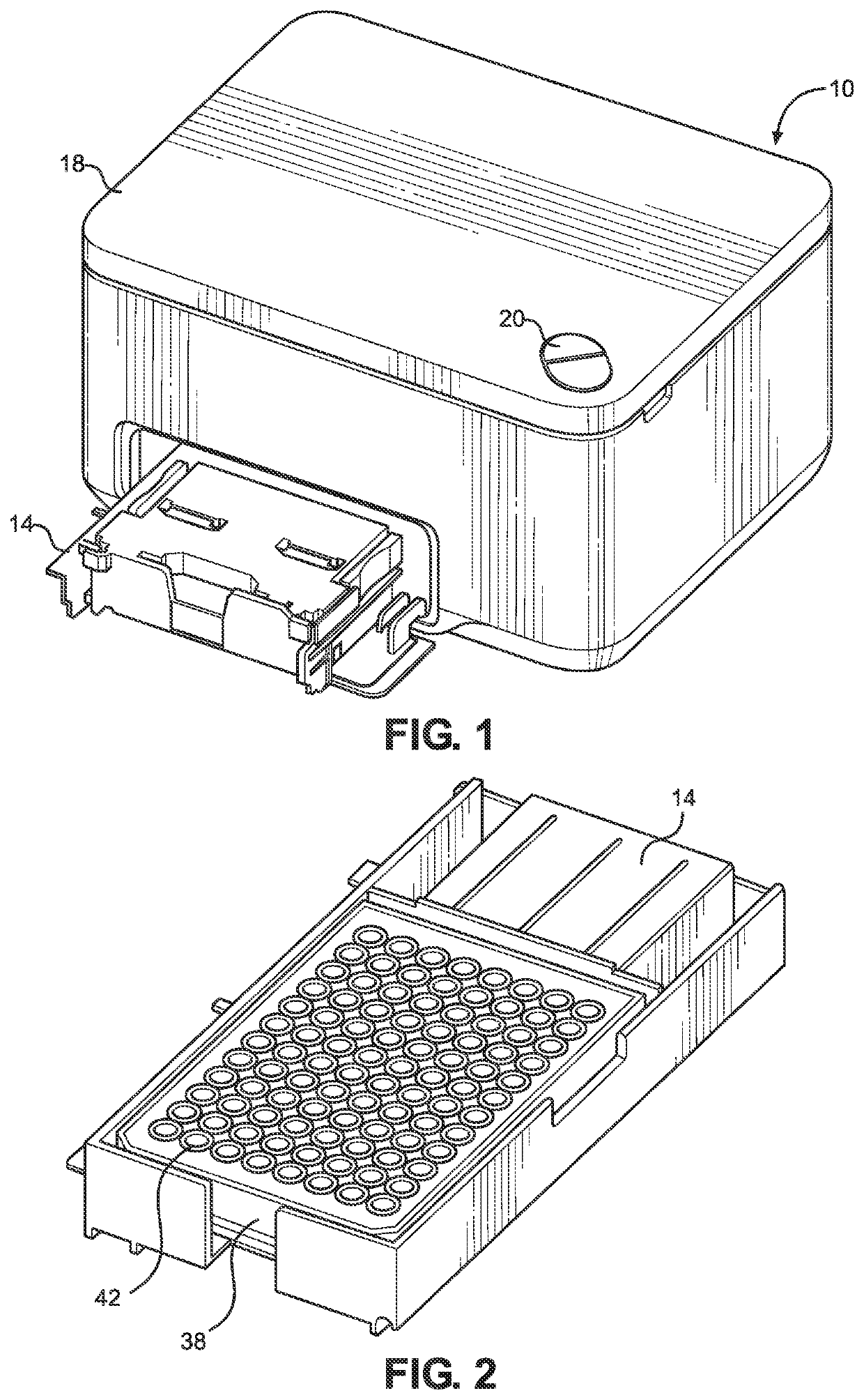
[0033]With reference to FIGS. 1-2 there is shown a digital dispense device 10 for accurately dispensing an amount of one or more fluids onto a substrate. Unlike the high-end digital dispense devices, the device 10 of the present invention is based on an ejection head that moves back and forth in a first x direction and a tray 14 for moving a substrate that moves back and forth in a second y direction orthogonal to the first direction during the fluid dispense operation. The disclosed device 10 can accept open and closed dispense heads rather than just open dispense heads. The tray 14 is adaptable to a wide variety of substrates including, but not limited to, micro-well plates, glass slides, electronic circuit boards and the like. FIG. 2 illustrates a tray 14 for holding a micro-well plate 38 containing wells 42 therein for use with the digital dispense device 10 to dispense fluid into the wells 42 of the micro-well plate 38 or onto the glass slides. The tray 14 may include adapters ...


PUM

PropertyMeasurementUnit
angleaaaaaaaaaa
volumeaaaaaaaaaa
transparentaaaaaaaaaa

Abstract

A pipette-fillable fluid reservoir body. The fluid reservoir body includes two or more discrete fluid chambers therein. At least one of the fluid chambers contains a pressure compensation device and at least another one of the fluid chambers is devoid of a pressure compensation device. Each of the fluid chambers is in fluid flow communication with a fluid supply via, and each of the fluid chambers have sidewalls and a bottom wall attached to the side walls, wherein the bottom wall slopes toward the fluid supply via. The fluid reservoir body also includes an ejection head support face in fluid flow communication with the fluid chambers for attachment of a fluid ejection device to the ejection head support face for ejecting fluid from the fluid chambers.

Description

TECHNICAL FIELD[0001]The disclosure is directed to chemical or biological assays, such as drug screenings, and in particular to improved fluid reservoir bodies used for chemical and biological assay applications in inexpensive fluid deposition devices.BACKGROUND AND SUMMARY[0002]In the medical field, in particular, there is a need for automated sample preparation and analysis. The analysis may be colorimetric analysis or require the staining of samples to better observe the samples under a microscope. Such analysis may include drug sample analysis, blood sample analysis and the like. Assay analysis of blood, for example, provides a number of different factors that are used to determine the health of an individual. When there are a large number of patients that require blood sample analysis, the procedures may be extremely time consuming. For assay analysis, such as drug screenings, it is desirable to deposit miniscule amounts of target reagents to evaluate their effect and performan...

Claims


Application Information

Patent Timeline
Patent Type & Authority Applications(United States)
IPC IPC(8): B01L3/00G01N35/10
CPCB01L3/527G01N35/1002B01L2200/026B01L2200/04B01L2200/0684B01L2300/0851B01L2300/021B01L2300/043B01L2200/06B41J2/17503B41J2/17506B41J2/17513B41J29/02B41J29/13B41J2/17553B41J2/17556B41J2/17509B41J2/1754B41J2/17566B41J2002/17573B01L3/0268G01N35/1016B41J2/17533G01N2035/1039B01L2200/0615
Inventor CARRITHERS, ADAM D.DEBOARD, BRUCE A.MARRA, III, MICHAEL A.NORASAK, SAM
Owner FUNAI ELECTRIC CO LTD
Learn More