
Nose cone vent design for inhalation device

a technology of inhalation device and nasal cavity, which is applied in the direction of inhalators, medical devices, other medical devices, etc., can solve the problems of inability to adapt, pulling too much vacuum from the nozzle, and each device cannot adapt to delivering a wide range of drugs via the nasal cavity rou

Pending Publication Date: 2022-09-22
FUNAI ELECTRIC CO LTD
View PDF0 Cites 0 Cited by
  • Summary
  • Abstract
  • Description
  • Claims
  • Application Information

AI Technical Summary

Benefits of technology

This patent text describes an improved nasal applicator for delivering drugs to a user's nasal cavity using a fluid jet delivery device. The device prevents drooling and accumulation of fluid, and also prevents fluid from drying out on the ejection head between uses. The technical effect of this patent is to provide a drug delivery device that can be used to provide a reduced pressure differential on the jet ejection head during use and that can be sealed to maintain a moist environment adjacent to the ejection head when not in use.

Problems solved by technology

Accordingly, conventional drug delivery devices are typically designed to deliver a specific drug to a nasal cavity and each device cannot be adapted for delivering a wide range of drugs via a nasal cavity route.
Accordingly, the drug delivery devices are typically designed for a specific drug and cannot be adapted to administer a different drug.
Studies have shown that pulling too much vacuum on nozzles of a fluid jet ejection head will pull fluid through the nozzles.
The effect of pulling fluid through the nozzles is worse when the ejection head is activated to eject fluid as a jet stream into a nasal cavity and the user inhales during the jetting operation.
When a moderate vacuum is pulled on a nozzle plate of a fluid jet ejection head during a fluid jetting sequence, fluid jetting is disturbed, and a desired fluid plume fails to form resulting in fluid drooling out of the nozzle plate and accumulating on the surface of the nozzle plate.
Another problem associated with using a fluid jet ejector device to administer drugs to a user's nasal cavity is that fluid may dry out on the ejection head between uses and interfere with fluid ejected through fluid nozzles on the ejection head causing misdirection of fluid and misfiring of fluid ejectors.

Method used


Image

  • Nose cone vent design for inhalation device
  • Nose cone vent design for inhalation device
  • Nose cone vent design for inhalation device

Examples


Embodiment Construction

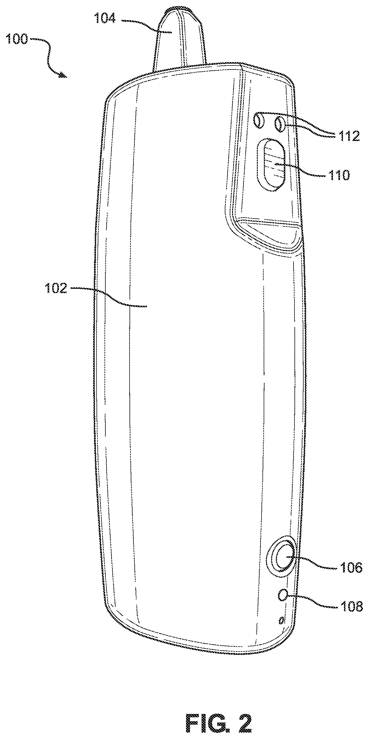
[0031]An illustration of a pharmaceutical drug delivery device 100 is illustrated in FIG. 2. The device includes a drug delivery device body 102, having a nose cone 104 attached to the drug delivery device body 102. A power button 106 is provided to activate the drug delivery device as indicated by an LED 108. During use of the device 100, a dispense button 110 is pressed and fluid delivery is indicated by LED's 112. When not in use, a cap may be used to cover the nose cone to prevent fluid from drying out on a fluid jet ejection head used to deliver the pharmaceutical drug to a user. The drug delivery device body 102 also contains a power source and a controller for controlling the ejection of fluid from the fluid jet ejection head.

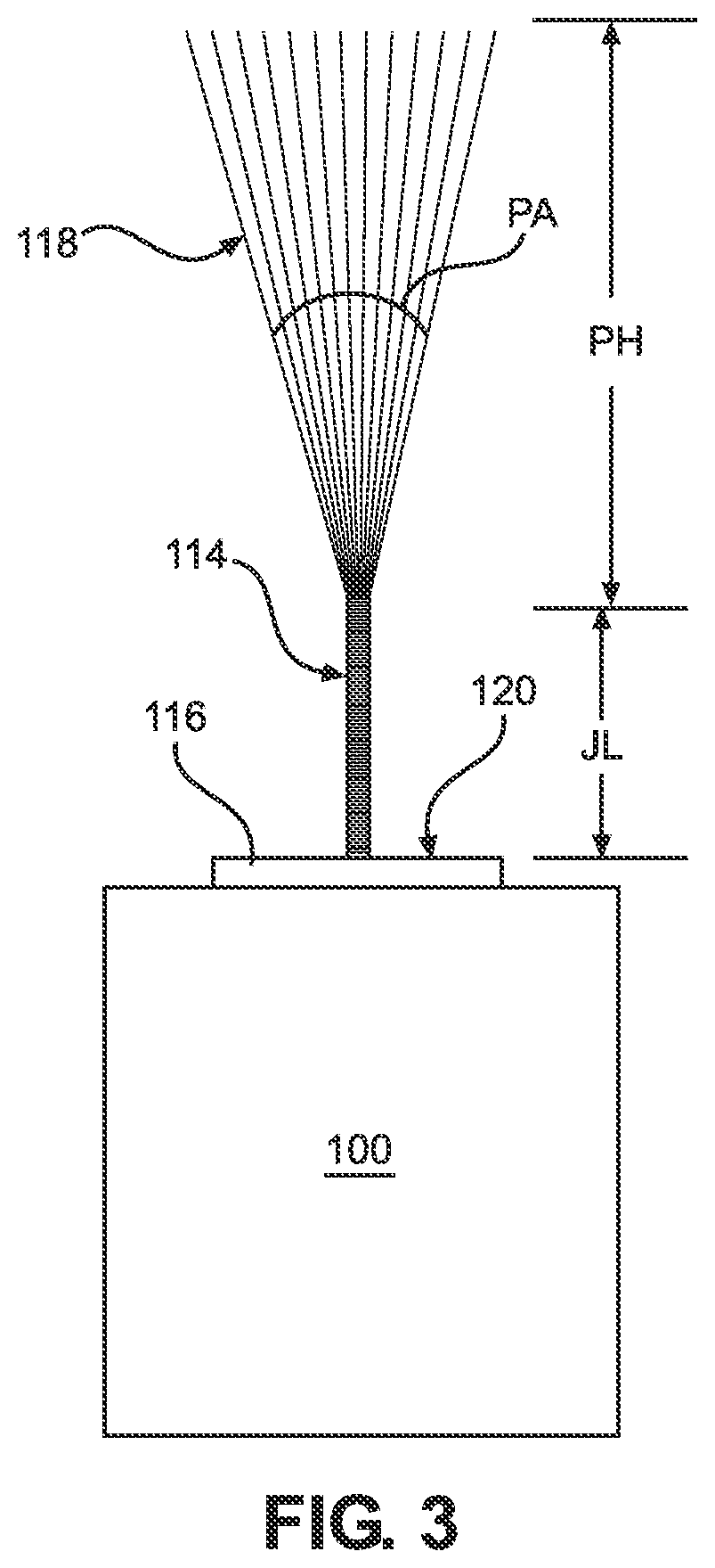
[0032]FIG. 3 is a schematic view of the operation of the drug delivery device 100 according to the disclosure. When the device 100 is activated by dispense button 110, a jet of fluid is emitted from the fluid jet ejection head 116 with a length of JL. As...


PUM


Abstract

A pharmaceutical drug delivery device. The drug delivery device includes a device body, a fluid outlet nose cone attached to the drug delivery device body, and a fluid jet ejection cartridge containing a liquid pharmaceutical drug is disposed in the drug delivery device body. A fluid ejection head is attached to the fluid jet ejection cartridge and the fluid ejection head is in fluid flow communication with the fluid outlet nose cone. The fluid outlet nose cone has a plurality of air flow channels open to an ambient atmosphere for providing a pressure differential between an inner area of the fluid outlet nose cone adjacent to the fluid ejection head and the ambient atmosphere.

Description

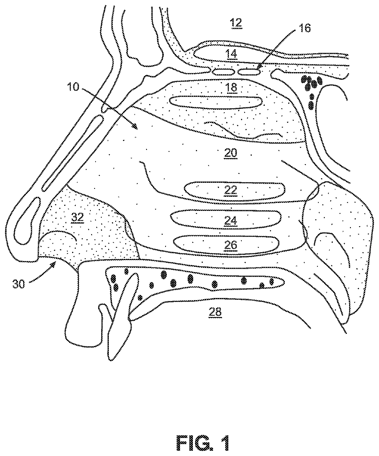
RELATED APPLICATION[0001]This application is a continuation-in-part of application Ser. No. 17 / 205,280, filed Mar. 18, 2021, now pending.TECHNICAL FIELD[0002]The disclosure is directed to inhalation drug delivery systems and in particular to inhalation devices that have an improved nose cone vent design to reduce fluid flooding of a fluid ejection head.BACKGROUND AND SUMMARY[0003]Nasal spray devices have become important methods for delivering drugs to patients. Such nasal spray devices are more convenient to use than the administration of drugs through intravenous (IV) injection. Nasal spray devices also provide higher bioavailability of drugs compared to oral administration of drugs. The absorption of drugs through nasal spray devices is more rapid compared to the absorption of drugs administered orally since drugs delivered by nasal spray devices directly enter the blood stream making their effect more immediate.[0004]FIG. 1 is a cross sectional view, not to scale, of anatomy of ...

Claims


Application Information

Patent Timeline
IPC IPC(8): A61M15/08A61M15/00
CPCA61M15/08A61M15/0025A61M2206/10A61M2205/8206A61M2205/583A61M15/025A61M11/005A61M2206/14A61M2205/3334B05B15/50B05B7/062B05B1/14
Inventor ANDERSON, JR., JAMES D.GIBSON, BRUCE D.JONES, BRIAN T.MILGATE, III, ROBERT W.SHIHARA, TETSUYA
Owner FUNAI ELECTRIC CO LTD
Learn More