Power conversion system with galvanically isolated high frequency link

a power conversion system and high frequency link technology, applied in the field of high frequency power electronics, can solve the problems of diluted power density of advanced turbines and generators, low power density of conventional electrical systems, and a large weight and volume of transformers,

Active Publication Date: 2010-03-16
GENERAL ELECTRIC CO
View PDF8 Cites 77 Cited by
  • Summary
  • Abstract
  • Description
  • Claims
  • Application Information

AI Technical Summary

Problems solved by technology

The low power density of conventional electrical systems has been a significant barrier to the deployment of ‘more electric’ systems for particular classes of ships.
Improvements in power densities that are achieved by advanced turbines and generators are often diluted by the need for bulky ancillary equipment, such as transformers.
Many modern power systems require large and heavy 50 Hz or 60 Hz conventional transformers.
The weight and volume of these transformers is a major barrier to the development of expanded electrical capabilities associated with certain future power system applications.
These architectures are disadvantageous in that they inherently necessitate a high level of complexity and part count.
A large number of cascaded cells are required with this approach due to limited voltage ratings of available silicon (Si) semiconductors.
The limited voltage rating and switching frequency of current high voltage IGBTs result in a large component count and low system performance.
However, at present state those SiC devices have a manufacturing yield that is lower than Si devices, and a cost that is higher than Si devices.
Significant challenges remain to developing such a smaller solid-state electronics transformer for a solid-state power substation (SSPS).
Conventional high power converter topologies, such as multi-level NPC converters, present significant design challenges at high frequencies due to complex device interconnections and packaging.
Parasitic inductances can lead to increased electrical stresses and degradation of performance;
Thermal management of high frequency transformers is a major challenge due to their reduced size;
Passive components, such as DC bus capacitors, input and output filters, and contactors can limit power densities.

Method used


Image

  • Power conversion system with galvanically isolated high frequency link
  • Power conversion system with galvanically isolated high frequency link
  • Power conversion system with galvanically isolated high frequency link

Examples


Embodiment Construction

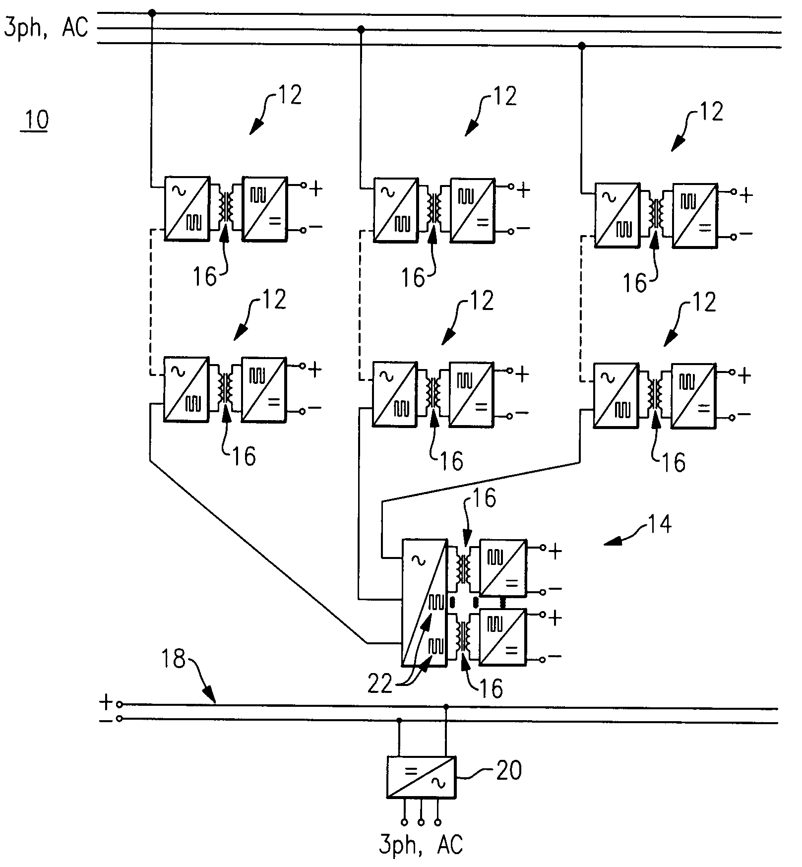
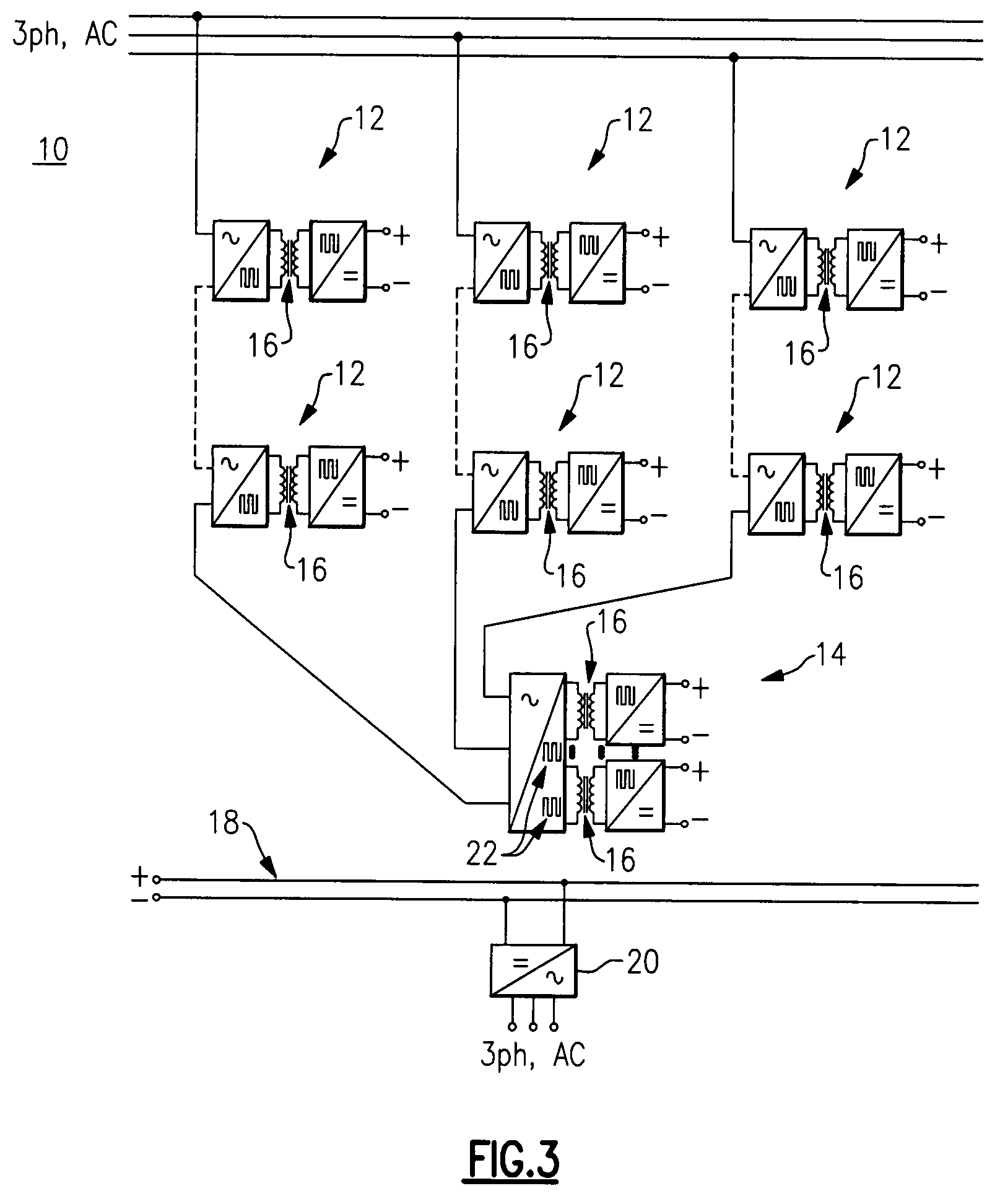
[0026]FIG. 3 illustrates a power conversion system (e.g. solid-state power substation (SSPS)) 10 with galvanically isolated high frequency links according to one embodiment of the present invention. The power conversion system 10 in one embodiment employs a hybrid (a mixed three-phase and single phase topology coupled with mixed SiC and Si devices) AC-DC stage that includes a plurality of single-phase AC-DC converters 12, and a three-phase AC-DC converter 14, to provide an advanced replacement for a conventional iron core transformer. A more detailed diagram of power conversion system 10 is illustrated in FIG. 4. The power conversion system 10 is based upon 1) rectification of high voltage AC to high voltage DC links by using an Si SCR or diode bridge 30 combined with SiC MOSFET H-bridges 17; 2) modular SiC MOSFET H-bridge DC-DC converters (enumerated 15 in FIG. 4) inverting the high voltage DC links to high frequency AC links prior to rectification; 3) modular high frequency transf...


PUM


Abstract

A power conversion system has a three-phase AC input, where each AC input phase is linked to a string of cascaded single-phase AC-DC converters placed in series with a three-phase AC-DC converter. Each single-phase AC-DC converter in one embodiment includes a silicon carbide (SiC) pulse width modulated MOSFET H-bridge that placed in series with the three-phase AC-DC converter that includes a silicon (Si) SCR bridge. The single-phase AC-DC converters and the three-phase AC-DC converter together in one embodiment include a mixed silicon-carbide (SiC) and silicon (Si) device topology.

Description

BACKGROUND[0001]The present invention is directed to high frequency power electronics, and more particularly to a power conversion system with a galvanically isolated high frequency link.[0002]The low power density of conventional electrical systems has been a significant barrier to the deployment of ‘more electric’ systems for particular classes of ships. Improvements in power densities that are achieved by advanced turbines and generators are often diluted by the need for bulky ancillary equipment, such as transformers.[0003]Many modern power systems require large and heavy 50 Hz or 60 Hz conventional transformers. The weight and volume of these transformers is a major barrier to the development of expanded electrical capabilities associated with certain future power system applications.[0004]High frequency “solid state transformers”, which are enhanced replacements of bulky line frequency iron core transformers have drawn considerable interest for utility distribution systems and...

Claims


Application Information

Patent Timeline
Patent Type & Authority Patents(United States)
IPC IPC(8): H02M5/45
CPCH02M7/217H02M2001/0074H02M2001/009Y02B70/1483Y02B70/10H02M1/0074H02M1/009
Inventor RAJU, RAVISEKHAR NADIMPALZHANG, RICHARD S.DATTA, RAJIBRITTER, ALLEN MICHAELSTEVANOVIC, LJUBISA DRAGOLJUB
Owner GENERAL ELECTRIC CO
Why Eureka
Try Eureka