Golf club head structure

a golf club and head structure technology, applied in the field of combined head structures, can solve the problems of low yield and time cost, and achieve the effect of preventing impact force and stress

Inactive Publication Date: 2010-03-23
ADVANCED INT MULTITECH CO LTD
View PDF25 Cites 133 Cited by
  • Summary
  • Abstract
  • Description
  • Claims
  • Application Information

AI Technical Summary

Benefits of technology

[0007]In view of the above problems, the present invention is directed to a club head structure, which is capable of enabling components to be fitted together through a simple process even when the components are deformed due to the problem of the casting process, and capable of preventing the impact force and stress generated by the hitting plate from influencing the junction surfaces for the components.
[0014]Through adopting the technical means of the present invention, the beneficial efficacies achieved are listed as follows. 1. Compared with the conventional snapping mode, when two assembly parts (the body and the plate) are deformed to result in the problem in their combination process, the structure of the present invention only needs a simple milling process to mill the butting surface between the two assembly parts to be flat according to the same angle, so as to perfectly combine them together, which is more preferred when a whole circle of butting surfaces are made on the same plane. Such a structural design of the present invention does not need the conventional shaping or complex CNC processing for making compensations, and thus saving the cost and the processing time, as well as improving the yield. 2. As for the club head structure of the present invention, a certain distance exists between the butting surface and the hitting surface, such that the present invention has a relatively far buffer region compared with the conventional butting structure, so as to reduce the impact force when hitting the ball. Furthermore, since it is relatively far away from the forced region (the butting surface is relatively far away from the hitting surface), the impact stress is relatively low, and the broken problem does not easily occur as well.

Problems solved by technology

As for such a combination manner, once the body or the plate is deformed due to an external factor, such as the problem occurring to the casting process, it is impossible for the two parts to be perfectly fitted with each other, so an additional shaping or complex computer numerical control (CNC) processing and other processes are required to make the two parts be fitted with each other, and thus this combined structure has disadvantages of low yield and time costing.

Method used


Image

  • Golf club head structure
  • Golf club head structure
  • Golf club head structure

Examples


Embodiment Construction

[0025]The preferred embodiments of the present invention are described below in detail with reference to the accompanying drawings.

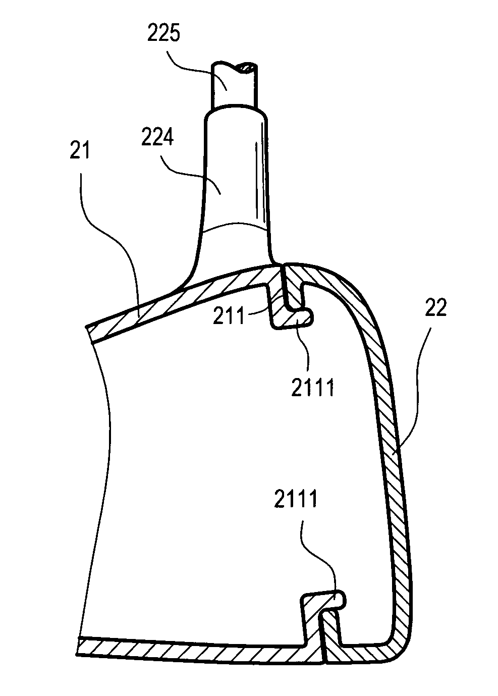
[0026]Referring to FIGS. 2A and 2B, the golf club head structure according to one embodiment of the present invention (in this embodiment, it is a wood head, and other forms such as an iron head and a putter are also suitable for the present invention) includes a casting of a body portion 21, a hitting plate portion 22, and a club body combining portion 224. The body portion 21 has a first junction surface 211 bent from a surface of the body portion 21 (the first junction surface 211 and the body portion 21 may be integrally formed through casting) and forming a first hook angle 212 with the surface of the body portion 21. The hitting plate portion 22 has a hitting surface 220 and a second junction surface 221 with a buffer region 223 existing there-between, and the second junction surface 221 forms a second hook angle 222 with a surface of the hitting p...


PUM


Abstract

A golf club head structure includes a body portion, a hitting plate portion, and a club body combining portion. The body portion has a first junction surface forming a first hook angle therewith. The hitting plate portion has a hitting surface and a second junction surface with a buffer region spaced there-between. The second junction surface forms a second hook angle with the hitting plate portion, and butts against and attaches to the first junction surface on the same plane. The club body combining portion is provided for combining a club body. Therefore, a joint structure with a junction portion as a plane, capable of not being located on the surface of the club head and spaced by a buffer region with the hitting surface, is formed, which is applicable for solving the combination problem of the junction surface on the same plane that the casting is deformed.

Description

[0001]This application claims the benefit of Taiwan Patent Application No. 096216722, filed on Oct. 5, 2007, which is hereby incorporated by reference for all purposes as if fully set forth herein.BACKGROUND OF THE INVENTION[0002]1. Field of the Invention[0003]The present invention relates to a combined club head structure of a golf club. More particularly, the present invention relates to a club head structure capable of overcoming the deformation of the assembly part and reducing the hitting impact and stress.[0004]2. Related Art[0005]Conventionally, when the golf club head is fabricated through a casting manner, it is usually formed by combining a plurality of pieces together, and the combining process generally includes a snapping mode and a butting mode. The conventional snapping mode is shown in FIG. 1A, a body joint 11 and a plate joint 13 with corresponding configuration are respectively disposed on the junction portion of a body 10 and the junction portion of a plate 12, so...

Claims


Application Information

Patent Timeline
Patent Type & Authority Patents(United States)
IPC IPC(8): A63B53/04A63B102/32
CPCA63B53/0466A63B53/047A63B53/0487A63B2053/0416A63B53/0416
Inventor HSU, CHUN-KAILEE, CHENG-TAO
Owner ADVANCED INT MULTITECH CO LTD
Why Eureka
Try Eureka