
Articulated orthosis providing lift support

a technology of orthosis and support, applied in the field of orthosis, can solve the problems of loss of function of the foot and ankle, loss of ability to bring the foot up, biomechanical deficit, etc., and achieve the effect of higher modulus of elasticity

Active Publication Date: 2010-03-23
ENGELMAN IAN K
View PDF27 Cites 28 Cited by
  • Summary
  • Abstract
  • Description
  • Claims
  • Application Information

AI Technical Summary

Benefits of technology

"The present invention provides an articulated orthosis with a joint that has a combination of a tension element and an elastic compression element. The tension element has a flat outer surface that acts as a pre-load, and the compression element has a flat inner surface that prevents interference between the parts. The compression surfaces are located so as to transmit forces to the compression element as a result of angular motion between the parts. The invention also provides an articulated orthosis with a first and second hinged parts, and a plurality of retaining walls that define a chamber for the compression element. The compression element can be adjusted for pre-load and resistance to moment force. The invention can be used in the design of a wrist hand orthosis."

Problems solved by technology

There are many pathologies that can lead to loss of function of the foot and ankle.
Often the biomechanical deficit will involve loss of dorsiflexion, i.e. the loss of ability to bring the foot up.
A range limiting joint limits the patients' ability to push the foot down (plantarflex) beyond a predetermined angle.
On the other hand, an excessive resistance to plantarflexion will force the knee forward, resulting in a less stable biomechanical situation.
An orthosis made of two parts presents a problem where, upon sliding the foot into the orthosis, the foot painfully hits, or otherwise gets snagged by, the foot portion.

Method used


Image

  • Articulated orthosis providing lift support
  • Articulated orthosis providing lift support
  • Articulated orthosis providing lift support

Examples


Embodiment Construction

[0039]Different aspects of the invention are described in terms of an AFO, which is the preferred embodiment, however it will be clear to the skilled in the art that the invention extends to other orthosis requiring adjustability in pre-loading and moment. Some preferred embodiments are described below.

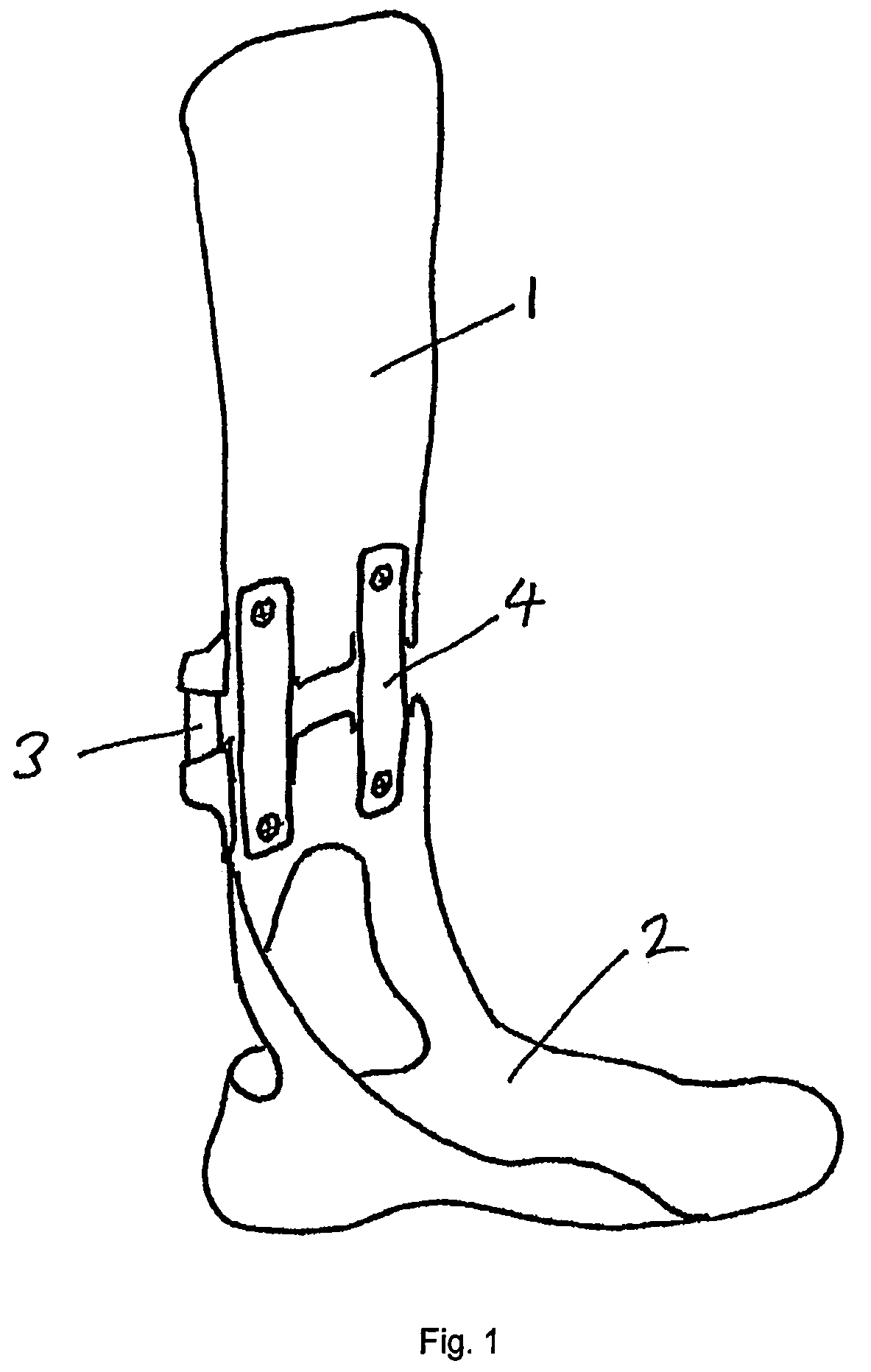
[0040]FIG. 1 is a general depiction of an ankle foot brace. A calf section 1 is articulated to a foot section 2 through two joints 3 and 4 respectively. While a single joint brace is also useful, the preferred embodiment calls for utilizing two joints.

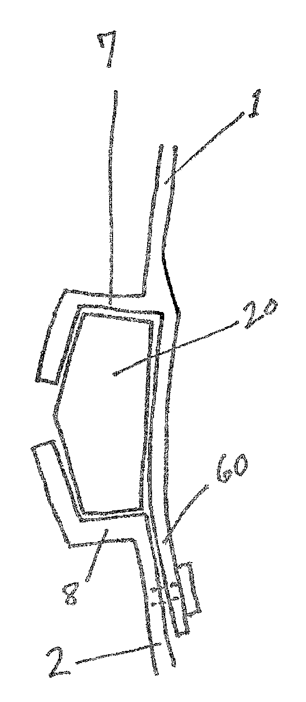
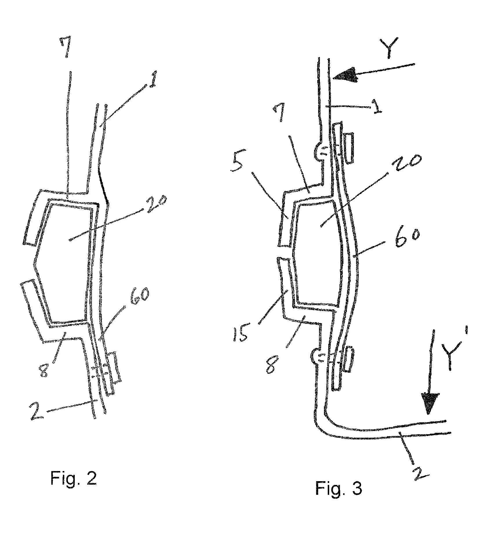
[0041]FIG. 2 depicts a cross section of the preferred embodiment of the invention in an unloaded state. The calf portion 1 and the foot portion 2 of the brace, each have a compression surface 7 and 8 respectively. A tensor 60 is coupled to the calf portion and to the foot portion and holds the portions together. In the preferred embodiment the tensor is coupled using fasteners, such as screws, rivets and the like. The tensor is made of r...


PUM


Abstract

An orthosis having at least one adjustable joint for articulating two hinged parts of the orthosis, the joint comprises a tensor for carrying the load applied between the two hinged parts. Compression surfaces coupled to the hinged parts are constructed to apply compression forces to a compression element when the angle between the two parts widens. Preferably the compression element comprises a block of resilient material. The joint allows adjustability of the unloaded angle between the hinged parts by varying the dimensions of the block, while selecting blocks having different compressional characteristics such as modulus of elasticity allows varying the degree of resistance to widening the angle between the two hinged parts. The joint is particularly advantageous in constructing an articulating leg brace.

Description

FIELD OF INVENTION[0001]The present invention relates generally to orthotic braces and more particularly to articulated braces having a joint with adjustable lift assist.BACKGROUND[0002]There are many pathologies that can lead to loss of function of the foot and ankle. By way of example, these include stroke, diabetes, Muscular dystrophy, multiple sclerosis and peripheral vascular disease, as well as others. Often the biomechanical deficit will involve loss of dorsiflexion, i.e. the loss of ability to bring the foot up. This situation is generically known as drop foot.[0003]The traditional solution is to provide a brace commonly known as an Ankle Foot Orthosis (AFO). The orthosis is commonly made out of one piece of plastic which is trimmed in the back so that it becomes flexible. This design is commonly known in the art as a Posterior Leaf Spring AFO.[0004]An improved orthosis is an articulated AFO. This orthosis has an upper portion (calf section) connected to a lower portion (foo...

Claims


Application Information

Patent Timeline
Patent Type & Authority Patents(United States)
IPC IPC(8): A61F5/00A61B19/00A61F5/28A61F5/37
CPCA61F5/0113A61F5/0127A61F5/013A61F2005/0169A61F2005/0179
Inventor ENGELMAN, IAN K.
Owner ENGELMAN IAN K
Learn More