Device for controlling power generated in vehicle

a technology for controlling devices and power generators, applied in the direction of generator control by field variation, electric generator control, dynamo-electric converter control, etc., can solve the problems of increasing the torque affecting the operation of the power generator, so as to reduce the voltage fluctuations and reduce the rotation speed

Inactive Publication Date: 2010-03-23
DENSO CORP
View PDF10 Cites 8 Cited by
  • Summary
  • Abstract
  • Description
  • Claims
  • Application Information

AI Technical Summary

Benefits of technology

[0009]The present invention has been achieved to solve the above-described issues. An object of the present invention is to provide a device for controlling power generation that can reduce voltage fluctuations and rotation speed decrease during gradual excitation control.
[0010]To solve the above-described issues, the device of the present invention controls the duty cycle of an excitation winding to be powered intermittently in a power generator and controls the output voltage from the power generator to a predetermined value. The device includes a power generation controlling circuit that, when the output voltage from the power generator is less than the predetermined value, gradually increases a value of the gradual excitation duty and gradually increases the excitation current. The gradual excitation duty is a limiting value for increasing and decreasing the excitation drive duty intermittently controlling the excitation winding. (i.e., the limit value indicates a maximum permitted rate for increasing and decreasing the duty of the excitation winding). On the other hand, when the output voltage from the power generator is greater than or equal to the predetermined value, the power generation controlling circuit decreases the value of the excitation drive duty and decreases the excitation current. The power generation controlling circuit has a decrease rate changing means that changes the rate at which the value of the gradual excitation duty is decreased. As a result, the rate at which the value of the gradual excitation duty is decreased can be changed depending on the status of the vehicle, such as usage of an electrical load. An optimal gradual excitation control can always be performed. Voltage fluctuations of the power generator and battery, and engine rotation reduction during idling can be prevented.
[0011]The device for controlling power generation is preferably mounted on the power generator and changes the decrease rate using the decrease rate changing means, based on a signal sent from an external controlling device. As a result, the amount of the electrical load and the status of the vehicle can be easily managed by the gradual excitation control.

Problems solved by technology

In a vehicle, engine-stalling or vibration occurs when an electrical load mounted in the vehicle suddenly increases so that a rapid increase of generated power is caused, therefore increasing the torque of the power generator.
In an actual vehicle, shaky rotation caused by disturbances, and fluctuations in a relatively small, periodically-operated electrical load occur during idling.
However, when the electrical load is re-introduced immediately after an amount of generated power decreases after the electrical load is disconnected, the stored duty has not yet decreased.
Accordingly, there occur problems, such as the power generator torque sharply increasing and idling speed decreasing.
In this way, the gradual excitation control function is adversely affected by the electrical load state of the vehicle (i.e., variation of an amount of the electrical load), causing voltage fluctuations and rotation decrease.

Method used


Image

  • Device for controlling power generated in vehicle
  • Device for controlling power generated in vehicle
  • Device for controlling power generated in vehicle

Examples


Embodiment Construction

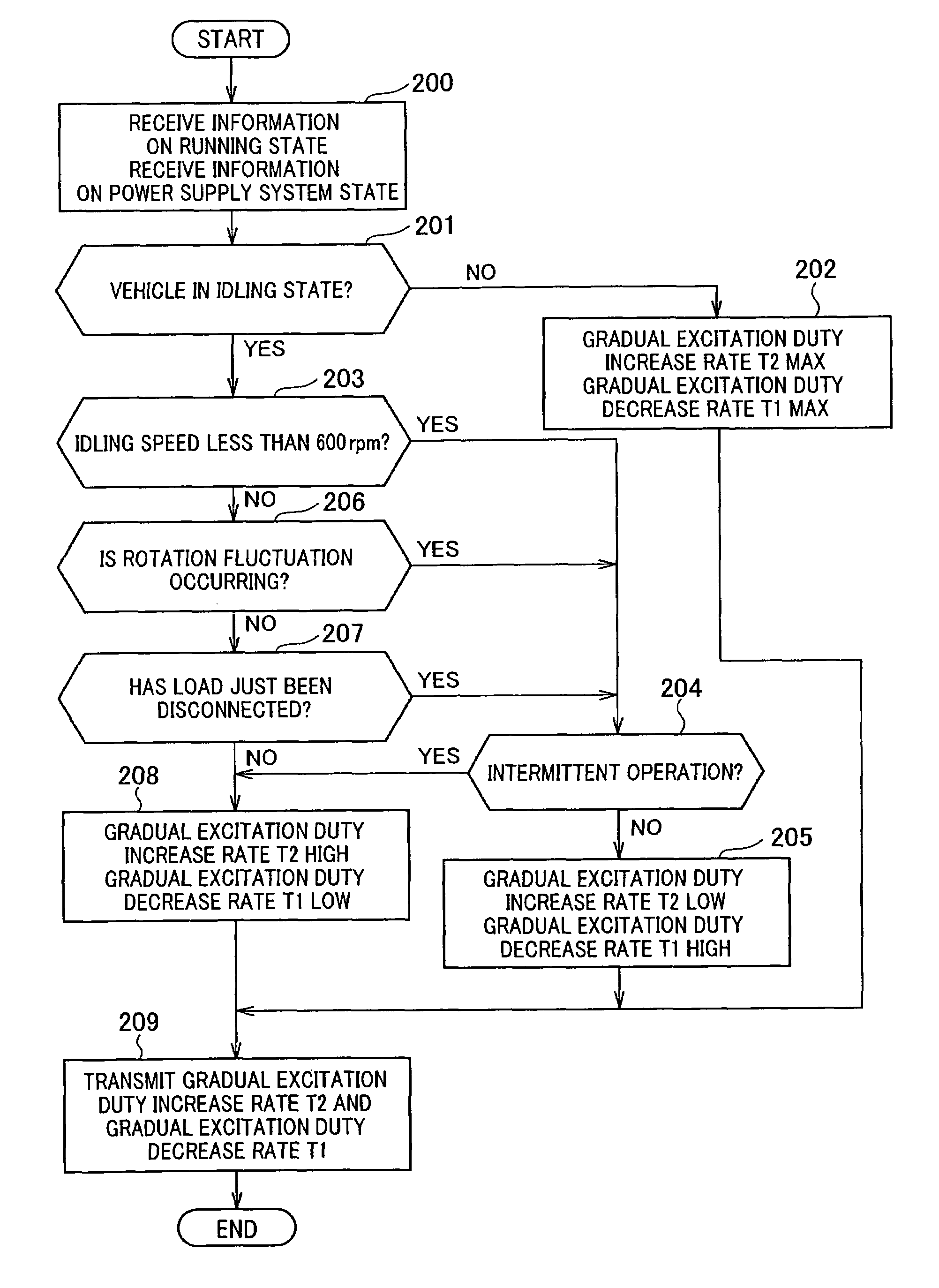
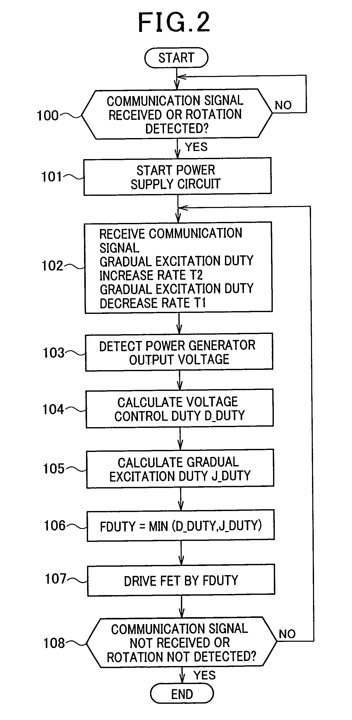
[0026]An embodiment of a vehicle power generation controller of the present invention will be described with reference to FIG. 1 to FIG. 5.

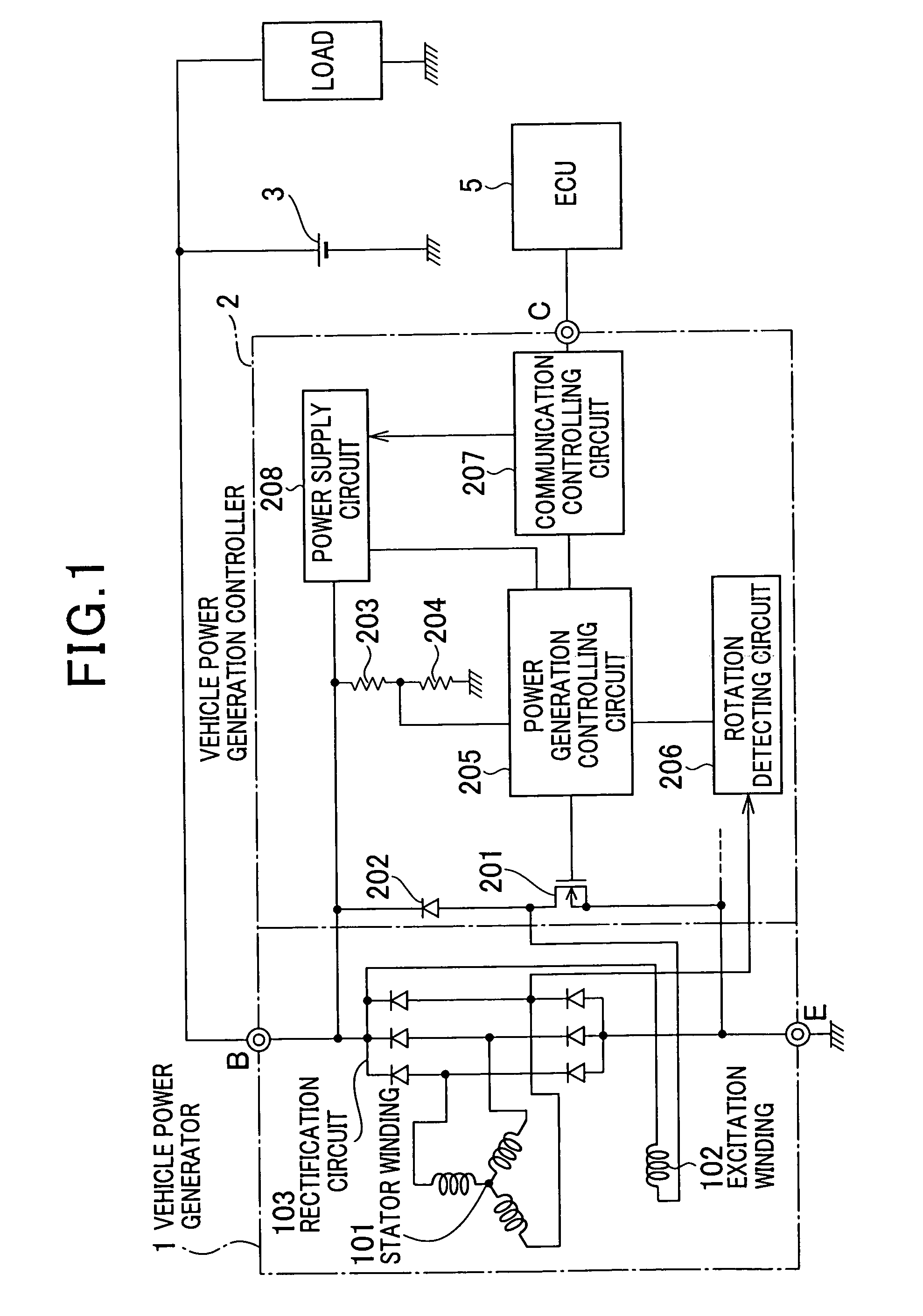
[0027]FIG. 1 is a diagram showing a configuration of a power generation controller according to the present embodiment. A connection between the power generation controller and power generator, a battery, and an electronic control unit (ECU) is shown. The power generator of the present embodiment is mounted in a vehicle and generates the necessary electric power for operation of the vehicle.

[0028]In FIG. 1, the power generation controller 2 is used to constrain a voltage (power generator output voltage VB) at an output terminal (called B terminal) of the power generator 1 to a predetermined regulated voltage setting value (for example, 14V). The power generation controller 2 has, in addition to the B terminal, a communication terminal (called the C terminal) and a ground terminal (called the E terminal). The B terminal is connected to a battery 3...


PUM


Abstract

A device for controlling vehicle power generation that controls duty cycle of an excitation winding in a vehicle power generator and controls an output voltage from the vehicle power generator to a predetermined value includes a power generation controlling circuit that, when the output voltage from the vehicle power generator is less than the predetermined value, gradually increases the value of a gradual excitation duty and gradually increases the excitation current, the gradual excitation duty being a limit value for increasing and decreasing an excitation drive duty intermittently controlling the electrification of the excitation winding, and in an opposite situation, gradually decreases a value of the excitation drive duty and gradually decreases the excitation current. The power generation controlling circuit changes the rate at which the value of the gradual excitation duty is decreased.

Description

CROSS-REFERENCE TO RELATED APPLICATION[0001]This application is related to Japanese Patent Application NO. 2007-209358 filed on Aug. 10, 2007, the contents of which are hereby incorporated by reference.BACKGROUND OF THE INVENTION[0002]1. Field of the Invention[0003]The present invention relates to a device for controlling power generated in a vehicle, and in particular, to a device that controls the output voltage from a power generator mounted in vehicles such as a passenger car and a truck.[0004]2. Description of the Related Art[0005]In a vehicle, engine-stalling or vibration occurs when an electrical load mounted in the vehicle suddenly increases so that a rapid increase of generated power is caused, therefore increasing the torque of the power generator.[0006]For preventing this problem, Japanese Patent Laid-open Publication No. 2006-121869 discloses a power generation controlling device that has a so-called gradual excitation control function. The gradual excitation control fun...

Claims


Application Information

Patent Timeline
Patent Type & Authority Patents(United States)
IPC IPC(8): H02P11/00H02P9/10
CPCH02J7/245H02M3/07H02P9/48Y02T10/92H02J7/2434
Inventor MAEHARA, FUYUKI
Owner DENSO CORP
Why Eureka
Try Eureka