Display apparatus and driving device for displaying
a technology of display apparatus and driving device, which is applied in the direction of instruments, static indicating devices, etc., can solve the problems of abnormal increase in display brightness, and inability to obtain proper contrast, etc., and achieve the effect of improving contras
- Summary
- Abstract
- Description
- Claims
- Application Information
AI Technical Summary
Benefits of technology
Problems solved by technology
Method used
Image
Examples
first embodiment
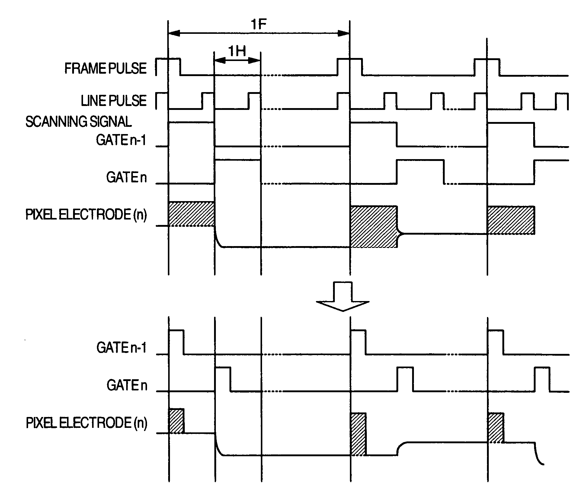
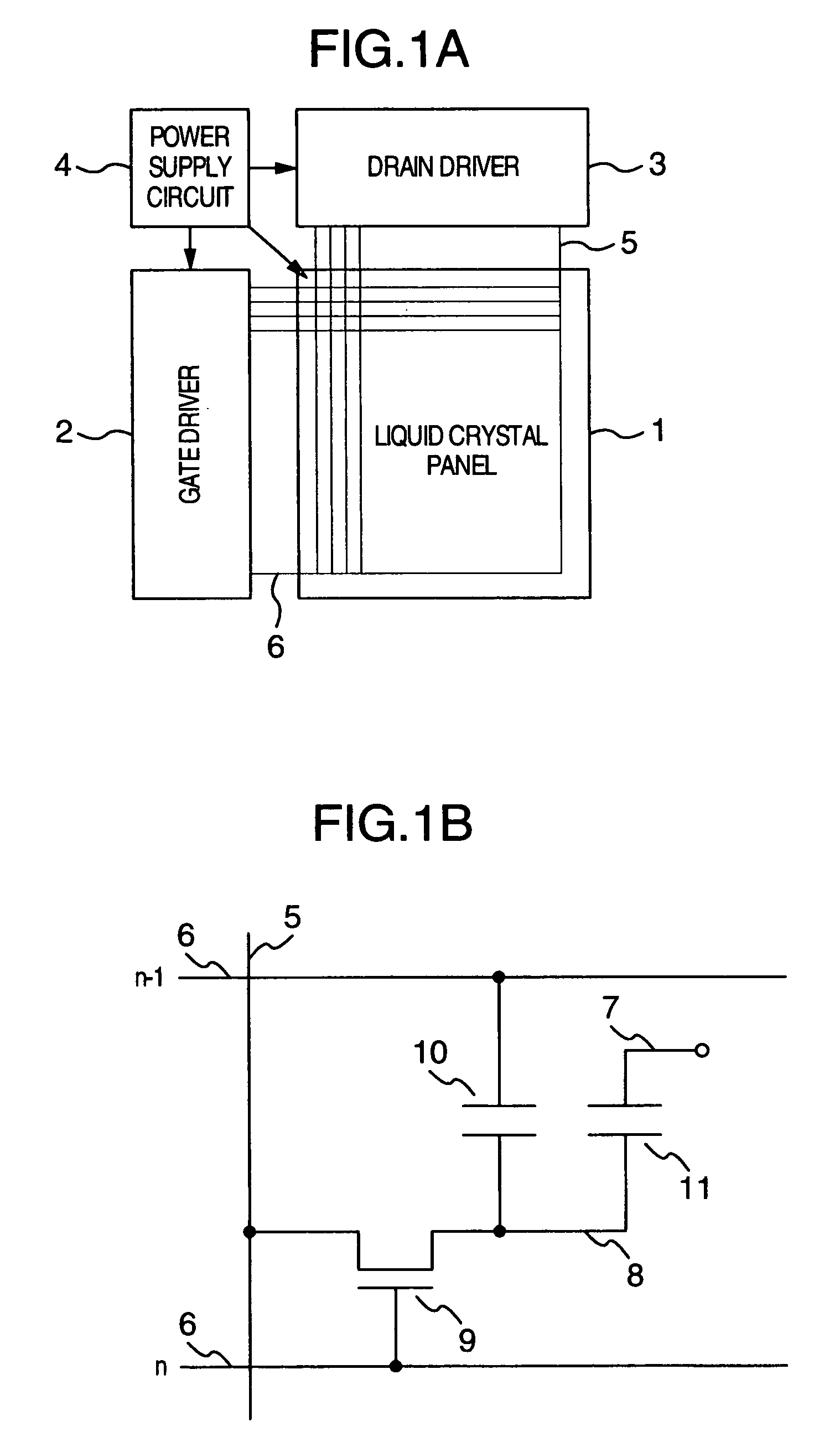
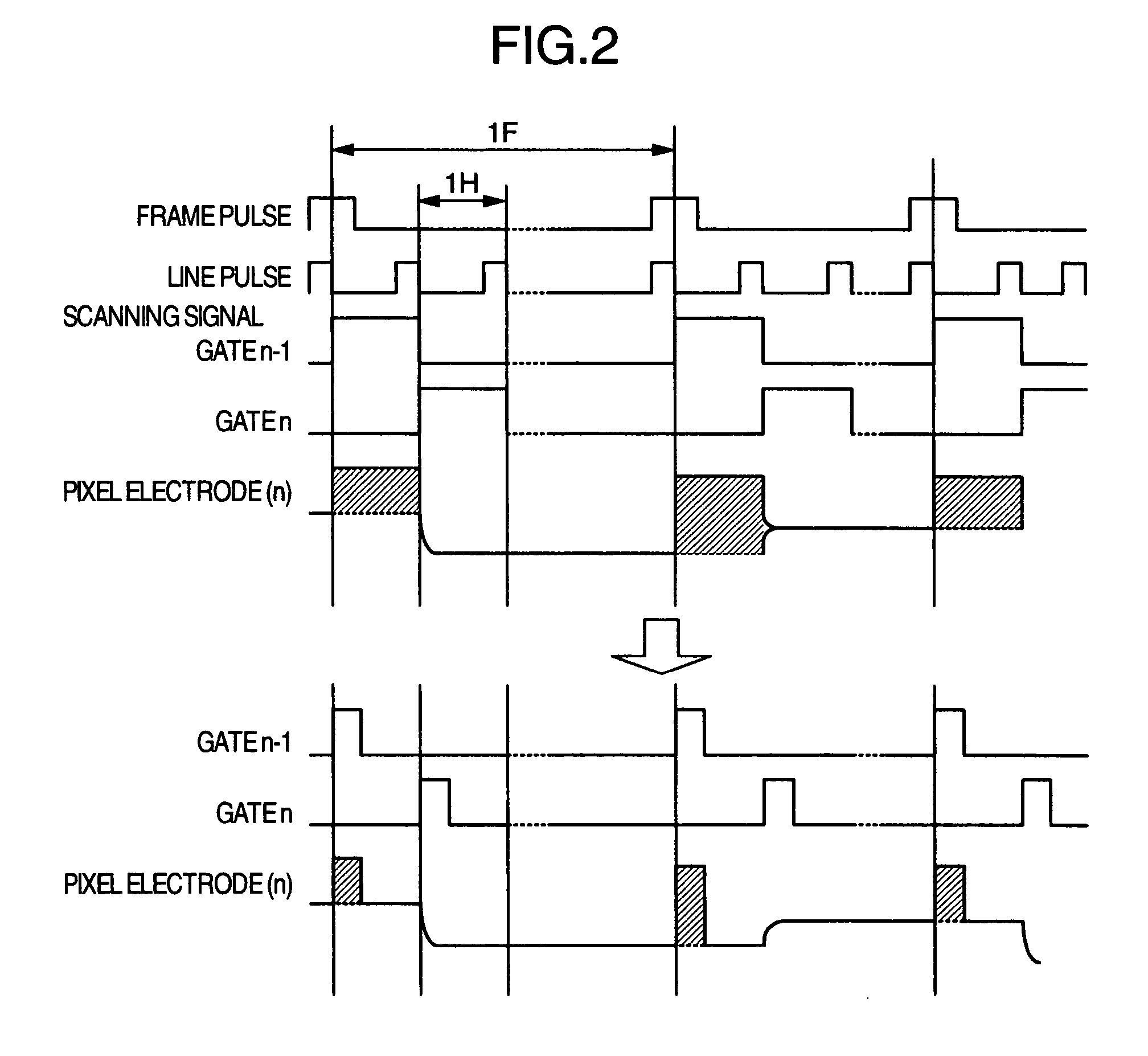
[0040]FIG. 4 is a block diagram showing a gate line drive circuit according to the invention. Reference numeral 801 designates a gate pulse signal, numeral 802 a scan data generating circuit for generating scan data, numeral 803 a level shifter, numeral 804 a gate line drive unit for outputting a gate pulse, numeral 805 a line pulse signal, numeral 806 a frame pulse signal and numeral 807 a pulse width signal. The gate driver 2 is supplied with the line pulse signal 805, the frame pulse signal 806 and the gate pulse width signal 807. The period of the pulse width signal 807 is equal to one horizontal period, and the high-level width (the time width during which the signal remains at high level) thereof is equal to the gate pulse width.
[0041] Based on the frame pulse signal 806 and the line pulse signal 805 input thereto, the scan data generating circuit 802 generates a timing of application of a gate line select voltage. In the case under consideration, the gate line select voltage ...
second embodiment
[0046] A gate line drive circuit according to the invention will be explained with reference to FIGS. 6 to 9.
[0047]FIG. 6 is a block diagram showing the gate line drive circuit according to the second embodiment of the invention. According to this invention, the gate pulse width is reduced by providing a non-overlap period (the period during which the select voltage is not input to any gate line). The gate pulse width can be varied by making the non-overlap period adjustable.
[0048] Numeral 808 designates a reference clock signal, numeral 809 information on a non-overlap period during which the select voltages for all the gate lines turn off, numeral 810 a non-overlap period generating unit for generating a non-overlap period waveform, and numeral 811 a register for storing the non-overlap period information 809. In place of the non-overlap period, the non-overlap timing (the timing of the gate pulse fall) may be set in a register. Also, in place of the non-overlap period, the time ...
third embodiment
[0064]FIG. 12 is a block diagram showing the gate line drive circuit according to the invention.
[0065] Numeral 1604 designates a partial LCD drive function information for partial display, numeral 1605 a non-scan timing generating unit for generating a non-scan timing for partial display, and numeral 1606 a register for storing the partial LCD drive function information 1604.
[0066] The gate driver 2 is supplied with the frame pulse signal 806, the line pulse signal 805 and the partial LCD drive function information 1604. The partial LCD drive function information 1604 includes a start line SS and an end line SE of the display area, and a scanning rate SCN of the non-display area (n=SCN). In the description that follows, the scanning rate is assumed to be once for every n frames.
[0067] The partial LCD drive function information 1604 input from an external source is stored in the register 1606. The data on the start line SS and the end line SE of the display area and the scanning ra...
PUM
| Property | Measurement | Unit |
|---|---|---|
| gray scale voltage | aaaaa | aaaaa |
| voltage | aaaaa | aaaaa |
| selection voltage | aaaaa | aaaaa |
Abstract
Description
Claims
Application Information
 - R&D
- Intellectual Property
- Life Sciences
- Materials
- Tech Scout
- Unparalleled Data Quality
- Higher Quality Content
- 60% Fewer Hallucinations
Browse by: Latest US Patents, China's latest patents, Technical Efficacy Thesaurus, Application Domain, Technology Topic, Popular Technical Reports.
© 2025 PatSnap. All rights reserved.Legal|Privacy policy|Modern Slavery Act Transparency Statement|Sitemap|About US| Contact US: help@patsnap.com


