Power flow control method for flexible multi-state switch connected to distributed power supply

A distributed power supply and power flow technology, which is applied in the direction of AC network with the same frequency from different sources, power transmission AC network, single-network parallel feeding arrangement, etc., can solve the problem of frequent action adjustment of flexible multi-state switches, single feeder power and voltage fluctuations, intermittent fluctuations of distributed power sources, etc., to achieve the effects of optimizing voltage distribution, load rate balance, and reducing power and voltage fluctuations

Active Publication Date: 2020-07-14
HEFEI UNIV OF TECH
View PDF4 Cites 7 Cited by
  • Summary
  • Abstract
  • Description
  • Claims
  • Application Information

AI Technical Summary

Problems solved by technology

[0003] However, there are intermittency and volatility problems in distributed power generation. Distributed power supply is directly connected to the feeder, which will cause power and voltage fluctuations to a single feeder
And due to the uncertainty of distributed power output, the feeder load rate changes frequently, and the port control setting of the flexible multi-state switch also needs to be adjusted frequently.

Method used


Image

  • Power flow control method for flexible multi-state switch connected to distributed power supply
  • Power flow control method for flexible multi-state switch connected to distributed power supply
  • Power flow control method for flexible multi-state switch connected to distributed power supply

Examples


Embodiment Construction

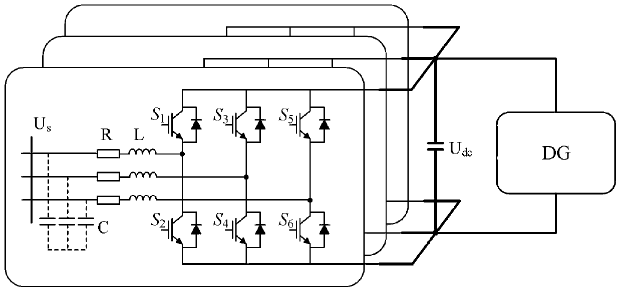
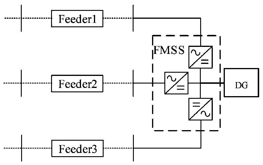
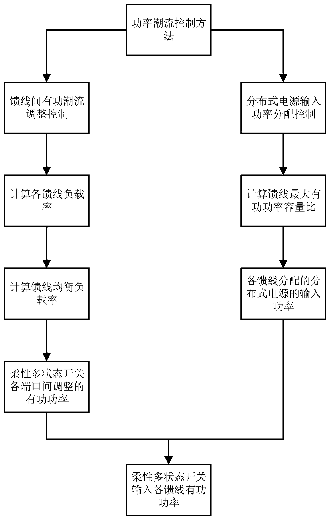
[0035] In this example, if figure 1 As shown, the flexible multi-state switch is used as a power electronic device, and the back-to-back voltage source converter is the main realization form of the flexible multi-state switch. Such as figure 2 As shown, in this embodiment, the flexible multi-state has three ports, and the flexible multi-state switch connected to the distributed power supply is connected in series at the ends of the three feeders, and the three different feeders are flexibly interconnected. A power flow control method for flexible multi-state switches connected to distributed power sources, such as image 3 As shown, proceed as follows:

[0036] Step 1. Construct the power model of the flexible multi-state switch connected to the distributed power supply and the mathematical model of the voltage source converter at each port;

[0037] Neglecting the self-loss of the flexible multi-state switch, when the flexible multi-state switch connected to the distribut...


PUM


Abstract

The invention discloses a power flow control method of a flexible multi-state switch connected to a distributed power supply. The method comprises the following steps: 1, constructing a power model ofthe flexible multi-state switch connected to the distributed power supply and a mathematical model of a voltage source type converter of each port; 2, calculating the load rate of each feeder line before the flexible multi-state switch is accessed and the load rate required to be balanced after the flexible multi-state switch is accessed, and deriving the active power adjusted by the connected flexible multi-state switch port voltage source type converter; 3, calculating the input active power of the distributed power supply allocated to each feeder line according to the active capacity ratioof each feeder line; 4, calculating the total active power output to each feeder line by the flexible multi-state switch connected to the distributed power supply. According to the invention, the load active power imbalance among the feeder lines can be adjusted, and the active power input by the distributed power supply is optimally distributed, so the power fluctuation caused by the access of the distributed power supply to a single feeder line can be reduced, and the intermittent energy consumption level is improved.

Description

technical field [0001] The invention relates to the technical field of flexible power distribution equipment control, in particular to a power flow control method of a flexible multi-state switch connected to a distributed power supply. Background technique [0002] With the large-scale access of distributed power to the power grid, the power flow of the distribution network is becoming more and more complicated, the problem of voltage exceeding the limit is becoming more and more prominent, and the reliability of power supply and the level of power quality are reduced. In 2009, Imperial College of Technology proposed the concept of soft normally open switch to replace the tie switch or section switch in the traditional distribution network. The flexible multi-state switch is developed based on the soft normally open switch. Compared with the only on and off states of the conventional switch, the flexible multi-state switch has the characteristics of flexible power adjustmen...

Claims


Application Information

Patent Timeline
Patent Type & Authority Applications(China)
IPC IPC(8): H02J3/06H02J3/36H02J3/48
CPCH02J3/06H02J3/36H02J3/48Y02E60/60
Inventor 余崇张国荣徐康波彭勃
Owner HEFEI UNIV OF TECH
Why Eureka
Try Eureka