
Communication device and communication method

a communication device and wireless technology, applied in the direction of pulse technique, electromagnetic wave modulation, synchronisation signal speed/phase control, etc., can solve the problems of inability to acquire diversity, performance decline, and a considerable period of time, and achieve the effect of preferable communication

Inactive Publication Date: 2010-03-23
FUJITSU LTD
View PDF48 Cites 15 Cited by
  • Summary
  • Abstract
  • Description
  • Claims
  • Application Information

AI Technical Summary

Benefits of technology

The patent text discusses the challenges of wireless communication in environments with fluctuating signal quality and the influence of screening objects. The technical effect of the patent is to provide a wireless communication device and method that can maintain high communication quality even in such environments, without any interruptions in wireless communications. The technology can be applied to devices based on MIMO and MISO architectures.

Problems solved by technology

In the transmission diversity, the STBC has a high spatial correlation depending on a location of the terminal, resulting a possibility of being unable to acquire the diversity.
In such a case, code orthogonality is not maintained, and the interference between the antennas rises, resulting in a possibility that the performance decreases.
On the other hand, as for the time diversity, it takes a considerable period of time up to such timing as to decrease the time correlation between the received signals when the fading fluctuations are slow.
It is therefore difficult to determine which is a superior wireless communication procedure, the STBC or the transmission diversity method, if there are the propagation path fluctuations and influence by a screening object between the wireless communication terminal device and the wireless communication base station.

Method used


Image

  • Communication device and communication method
  • Communication device and communication method
  • Communication device and communication method

Examples


working examples

[0203]

[0204]The five working examples of the embodiment of the receiving-side wireless communication device will be described. Before explaining the receiving-side wireless communication device, one working example of the transmitting-side wireless communication device will be described with reference to a processing flowchart shown in FIG. 23.

[0205]Note that the demodulation unit 2, the bit determining unit 3, the diversity method designating unit 4 and the STBC-or-time diversity encoding unit 5 illustrated in FIG. 8 can be realized as a program on a CPU (Central Processing Unit) or a DSP (Digital Signal Processor). Part of these components may also be configured by dedicated arithmetic circuits.

[0206]The diversity changeover process executed by the transmitting unit in FIG. 8 will be explained with reference to FIG. 23.

[0207]FIG. 23 is a flowchart of the diversity changeover process by the transmitting unit. In this process, at first, the feedback information received from the par...

first working example

[0209]A first working example corresponds a working example when applying the formula (1) of the system principle in the case of the communication device based on the MISO architecture and a working example when applying the formula (12) of the system principle in the case of the communication device based on the MIMO architecture, respectively.

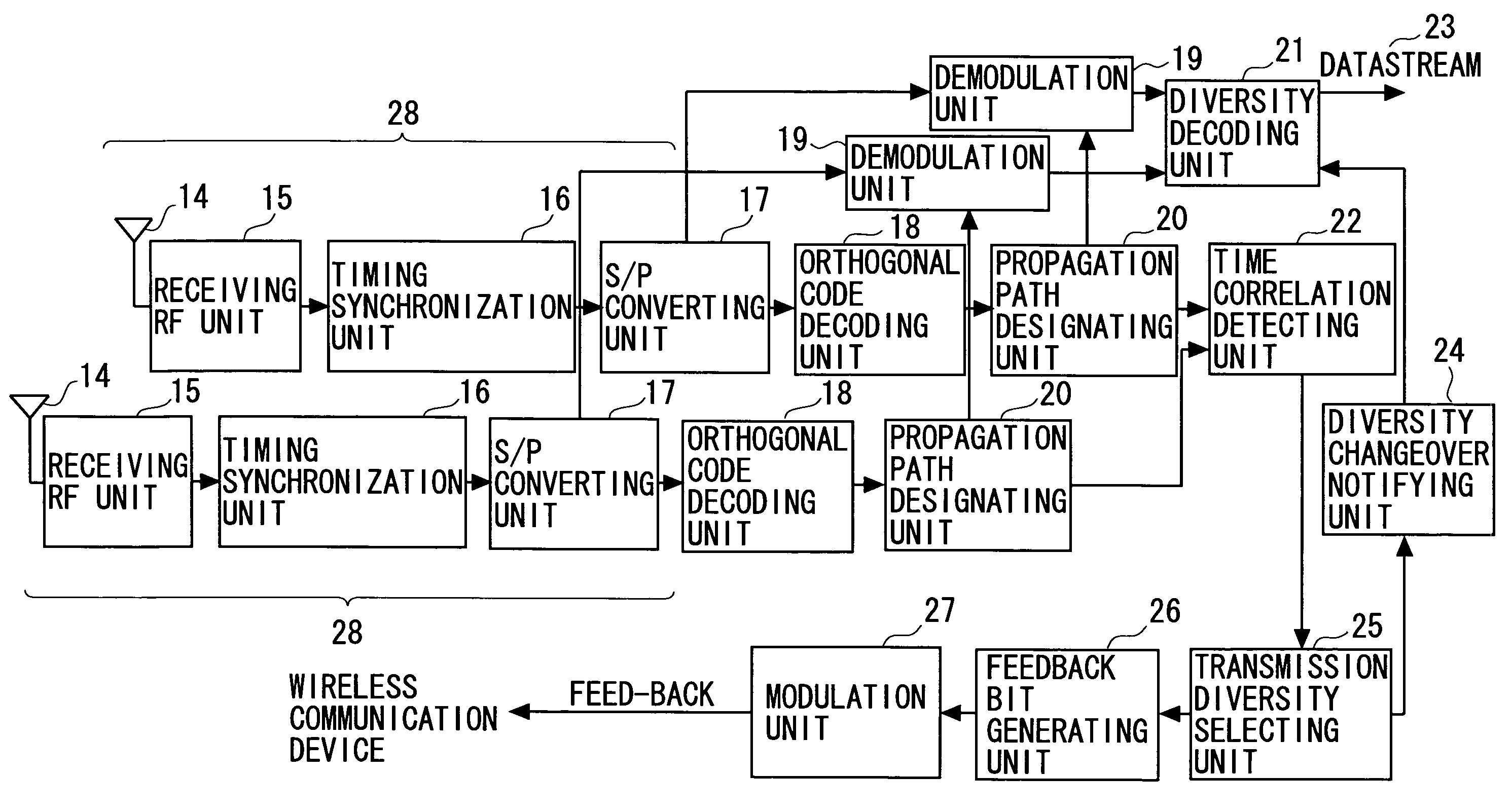
[0210]The first working example of the receiving unit will be described with reference to a flowchart shown in FIG. 11.

[0211]It should be noted that the propagation path estimating unit 20, the diversity decoding unit 21, the time correlation detecting unit 22, the diversity changeover notifying unit 24, the transmission diversity selecting unit 25, the feedback bit generating unit 26 and the modulation unit 27 in FIG. 10 can be realized as a program on the CPU (Central Processing Unit) or the DSP (Digital Signal Processor). Part of these components may be, however, built up by dedicated arithmetic circuits.

[0212]FIG. 11 is a flowchart of the...

second working example

[0215]A second working example corresponds a working example when applying the formula (9) of the system principle in the case of the communication device based on the MISO architecture and a working example when applying the formula (13) of the system principle in the case of the communication device based on the MIMO architecture, respectively.

[0216]The second working example will be described with reference to a flowchart, shown in FIG. 12, of the processing by the receiving unit. In FIG. 12, the same processes as those described in the first working example are marked with the same reference symbols as those in FIG. 11, and their explanations are omitted. The second working example is different from the first working example, wherein steps S2 and S3 are replaced by steps S2A and S3A.

[0217]The following are processes in steps S2A and S3A. In the case of the MISO architecture, the time correlation detecting unit 22 calculates the time correlations of the received signals from the ...


PUM


Abstract

There is provided a radio communication device having a high quality and accuracy regardless of fluctuation degree of the transmission path characteristic. The radio communication device estimates the fluctuation speed of the transmission path characteristic from the time correlation of the reception signal, judges the diversity technique used between the communication devices from the estimated value, and feeds back the judgment information so as to switch the diversity between the communication devices, thereby increasing the diversity gain. The feedback information is minimized by defining a correspondence table. Moreover, diversity switching is performed at a timing considering a control delay and a propagation path delay so as to prevent an instantaneous disconnection of the communication.

Description

CROSS-REFERENCE TO RELATED APPLICATION[0001]This is a continuation of Application PCT / JP2005 / 004570, filed on Mar. 15, 2005, now pending, the contents of which are herein wholly incorporated by reference.BACKGROUND OF THE INVENTION[0002]1. Field of the Invention[0003]The present invention relates to a wireless transmitting device and a wireless transmitting method.[0004]2. Description of the Related Art[0005]A short-break-free wireless communication technology applicable to voice speeches, radios, low-pixel television broadcasting, etc has been examined over the recent years. The technology under the examination is the wireless communication technology with no time delay larger than a predetermined limit value. Obstacles against realizing the short-break-free wireless communications are interference between radio signals received via different propagation routes and screening on the propagation path. These phenomena are called fading and shadowing. A wireless communication method an...

Claims


Application Information

Patent Timeline
Patent Type & Authority Patents(United States)
IPC IPC(8): H04L1/02H04J99/00
CPCH04B7/063H04L7/08H04B7/0669H04B7/0689
Inventor YOKOYAMA, HITOSHI
Owner FUJITSU LTD
Learn More