Wireless packet communication method and wireless packet communication apparatus

a wireless packet and communication method technology, applied in the field of wireless packet communication methods and wireless packet communication apparatus, can solve the problems of large leakage power into the frequency band used between one radio channel and the other radio channel, poor throughput, and poor quality of communication, so as to improve the effective throughput and improve the quality of communication. , the effect of high-quality communication

Inactive Publication Date: 2010-07-20
NIPPON TELEGRAPH & TELEPHONE CORP
View PDF6 Cites 6 Cited by
  • Summary
  • Abstract
  • Description
  • Claims
  • Application Information

AI Technical Summary

Benefits of technology

[0022]Accordingly, the transmission rates are individually managed for each receiver terminal, the packet time lengths defined by the packet sizes and transmission rates are checked for the respective data packets, and the transmissions of the plurality of data packets whose packet time lengths are approximately equal to each other are commenced simultaneously. Therefore, before start of receptions of acknowledgment packets, the transmissions of all the data packets can be completed. Accordingly, even when power leakages occur between the radio channels, acknowledgment packets can be received without receiving any effect of the power leakage. Further, since a plurality of data packets to different destinations can be transmitted simultaneously, the transmission wait time until a plurality of data packets to be transmitted are provided on a transmission buffer can be shortened and effective throughput is improved.
[0039]Here, Nch and Np are detected to determine use of a plurality of radio channel and of the MIMO according to conditions, thereby realizing preferable communication. That is, when a plurality of data packets are transmitted simultaneously by use of a plurality of radio channels, a plurality of idle radio channels are effectively used so as to provide high-quality communication and improve effective throughput. In addition, with the use of the MIMO, effective throughput can be improved even when there is only one idle radio channel.

Problems solved by technology

Therefore, although the transmission rate in the PHY layer increases, throughput is not improved significantly.
However, in the case where center frequencies of a plurality of radio channels to be used simultaneously come close to each other, an effect of leakage power leaking into the frequency band which is used between one radio channel and the other radio channel becomes great.
When the transmit-side station tries to receive the acknowledgement packet, an effect of leakage power from other radio channels where the packets are transmitted simultaneously becomes a problem.
Under such a condition, even though transmissions are performed simultaneously by use of a plurality of radio channels, throughput can not be expected to be improved.
However, in a wireless LAN system or the like, the data sizes of data frames to be input from a network are not constant.
For this reason, although a plurality of data packets are transmitted simultaneously as shown in FIG. 19, the difference in the packet time lengths of the respective data packets occurs, so that it is very likely to fail to receive an ACK packet.
However, in this case, since transmissions have to be delayed until a plurality of data frames having the same sizes are provided on a buffer, the transmissions can not be effectively commenced and reduction in effective throughput can not be avoided.
In addition, when data frames having the same sizes do not appear for a long time, a transmission delay is increased.
In this case, if data packets which are configured by data frames having the same sizes but have different receiver addresses are transmitted simultaneously, the transmissions are not completed simultaneously and the receptions of acknowledge packets fail due to leakage power.

Method used


Image

  • Wireless packet communication method and wireless packet communication apparatus
  • Wireless packet communication method and wireless packet communication apparatus
  • Wireless packet communication method and wireless packet communication apparatus

Examples


Embodiment Construction

[Configuration Example of Wireless Packet Communication Apparatus]

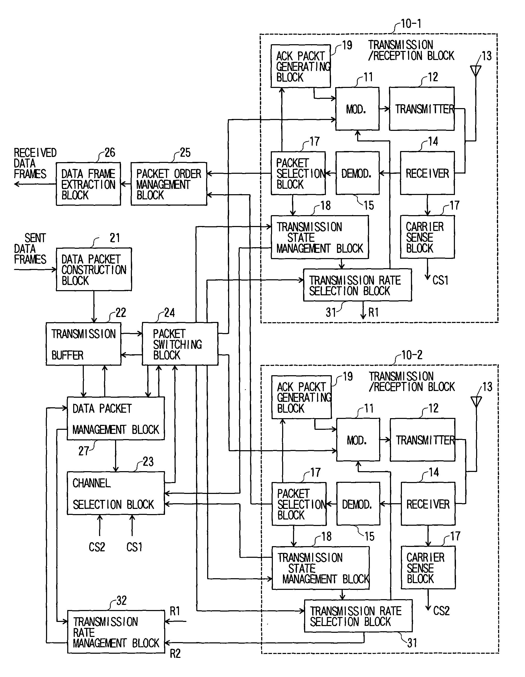
[0062]FIG. 1 shows a configuration example of a wireless packet communication apparatus of the present invention. Here, it is assumed that data packets are transmitted through wireless links between more than three STAs. As these STAs, for example, radio base stations and radio terminals can be assumed, which constitute a wireless LAN system in conformity with IEEE802.11 standards.

[0063]In the drawing, the radio base station of the present configuration example includes a plurality of transmit / receive processing blocks 10-1, 10-2, . . . , a data packet construction block 21, a transmission buffer 22, a channel selection block 23, a packet switching block 24, a packet order management block 25, a data frame extraction block 26, a data packet management block 27, and a transmission rate management block 32. Each of the transmit / receive processing blocks 10-1, 10-2, . . . performs radio communication through radio channe...


PUM


Abstract

A plurality of types of available transmission rates to be used for transmission of data packets are individually managed for each receiver terminal. When there are a plurality of data packets to be transmitted onto a transmission buffer and when it is possible to transmit said plurality of data packets simultaneously, the packet sizes representative of the data amounts of the respective data packets are referred to as well as the transmission rates of the respective data packets associated with the receiver terminals. The packet time lengths (transmission times) defined by the packet sizes and transmission rates are checked for the respective data packets. A plurality of data packets whose packet time lengths are approximately equal to each other are selected regardless of their receiver terminals. The transmissions of the plurality of selected data packets are commenced simultaneously by use of a plurality of radio channels.

Description

CROSS-REFERENCE TO RELATED APPLICATION[0001]This application is based upon and claims the benefit of priority from Japanese Patent Application Nos. 2003-317099, filed on Sep. 9, 2003, and No. 2003-351161, filed on Oct. 9, 2003, the entire contents of which are incorporated herein by reference.TECHNICAL FIELD[0002]The present invention relates to a wireless packet communication method of simultaneously transmitting data packets addressed to different destinations, using a plurality of radio channels and Multiple Input Multiple Output (hereinafter MIMO) among a plurality of stations (hereinafter STAs) and a wireless packet communication apparatus.BACKGROUND ART[0003]In a conventional wireless packet communication apparatus, only one radio channel to be used is determined in advance and it is detected whether the radio channel is idle or not (carrier sense) prior to transmitting data packets. Only when the radio channel is idle, only one data packet is transmitted. By such a control, o...

Claims


Application Information

Patent Timeline
Patent Type & Authority Patents(United States)
IPC IPC(8): H04W4/00H04W72/00H04W40/00H04L12/413H04J1/16G01R31/08H04L29/08H04W16/28H04W28/06H04W28/16H04W72/04H04W72/08H04W74/08H04W84/12
CPCH04W28/16
Inventor SAITO, KAZUYOSHIKUMAGAI, TOMOAKIOTSUKI, SHINYANAGATA, KENGOAIKAWA, SATORU
Owner NIPPON TELEGRAPH & TELEPHONE CORP
Why Eureka
Try Eureka