X-ray CT apparatus

a computed tomography and x-ray technology, applied in the field of x-ray ct (computed tomography) apparatus, can solve the problems of impracticality of imaging methods, increased stress on the subject, and complicated control of x-ray ct apparatus, so as to reduce the positional offset of the subject and reduce the stress on the subject.

Inactive Publication Date: 2010-03-23
GE MEDICAL SYST GLOBAL TECH CO LLC
View PDF11 Cites 14 Cited by
  • Summary
  • Abstract
  • Description
  • Claims
  • Application Information

AI Technical Summary

Benefits of technology

[0008]When applying the prospective imaging method, however, a scan has to be made in synchronization with a specific cardiac phase in which the motion of the heart is slow, and therefore, the subject's cardiac phase must be constantly checked by monitoring the subject's electrocardiographic waveform or the like to determine when to start a scan for each scan, thus complicating control of the X-ray CT apparatus. When applying the retrospective imaging method, the subject is exposed to X-rays continuously and over a long time, and the exposure dose to the subject is increased. Especially when the retrospective imaging method is combined with contrast imaging, the contrast agent injected into the subject flows relatively fast, so that the total dosage of the contrast agent, and hence, stress on the subject is further increased, thus making such an imaging method impractical.
[0009]The present invention has been made in view of such circumstances, and its object is to provide an X-ray CT apparatus for scanning a subject with a plurality of kinds of X-rays having energy distributions different from one another, in which a subject's positional offset can be reduced among a plurality of kinds of tomographic images representing the same slice obtained by the scans by a simple control scheme while reducing stress on the subject.
[0021]In its twelfth aspect, the present invention provides the X-ray CT apparatus in any one of first through eleventh aspects, further comprising: image producing device for processing first projection data acquired by said first scan and second projection data acquired by said second scan to produce an enhanced image in which a difference between a tomographic image from said first projection data and a tomographic image from said second projection data representing mutually the same slice is enhanced.
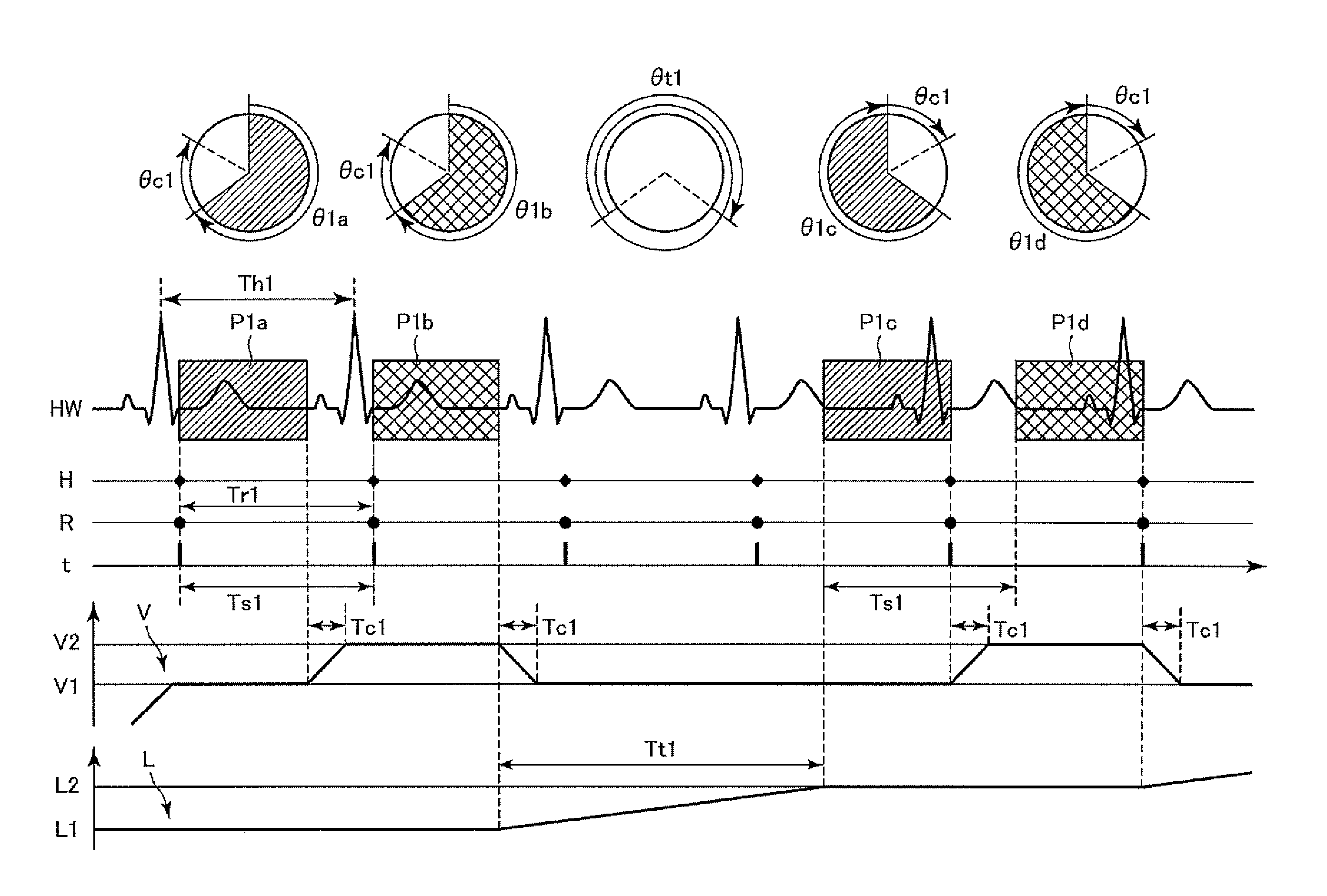
[0040]The “cardiac cycle identifying device” may include, for example, device of calculating a cardiac cycle by acquiring electrocardiographic waveform signals or electrocardiological synchronization signals that represents heart beat synchronization signals from an electrocardiograph, or by acquiring heart beat synchronization signals from a heart rate monitor or a pulsemeter, and device of acquiring information representing a cardiac cycle from an electrocardiograph, a heart rate monitor or a pulsemeter. When the “cardiac cycle identifying device” is of a type that acquires heart beat synchronization signals to calculate a cardiac cycle, it may calculate a cardiac cycle as the time between two consecutive heart beat synchronization signals, or as the time obtained by calculating the time between two consecutive heart beat synchronization signals in three or more consecutive heart beat synchronization signals for each combination of the two consecutive heart beat synchronization signals therein, and averaging the times between the signals in such combinations. If the latter is employed, and when the time between the signals represents an extremely long or short cardiac cycle as compared with the previously calculated cardiac cycle, that is, for example, when the time between the signals represents a cardiac cycle 20% longer or shorter than the previously calculated cardiac cycle, the time between the signals is desirably unused in calculating a new cardiac cycle. Thus, even if the heart beat becomes out of order due to, for example, arrhythmia of the subject, the calculated cardiac cycle can be prevented from extreme variation, thus enabling identification of a more substantial cardiac cycle. Moreover, the “cardiac cycle identifying device” may calculate a cardiac cycle by counting the number of heart beat synchronization signals within a given period of time, and dividing the given period of time by the counted number of heart beat synchronization signals.
[0044]According to the X-ray CT apparatus of the present invention, a subject's cardiac cycle is identified by the cardiac cycle identifying device prior to a first scan; a time interval from the start of a first scan to the start of a second scan is set by the scan start time interval setting device to a time approximately the same as the aforementioned identified cardiac cycle; and the X-ray data collecting system is controlled by the scan control device to start the first and second scans at the set time interval and perform each of the scans within one cardiac cycle while rotating the X-ray data collecting system in a constant cycle of rotation such that cardiac phase coverage for the first scan approximately matches that for the second scan. Therefore, two kinds of projection data can be collected by only two consecutive scans, in which data temporal changes involved in subject's cardiac motion during the scans are approximately the same as each other, that is, in which data the aforementioned subject's temporal change appears as distortion approximately the same as each other on reconstructed tomographic images, but does not appear as a difference between tomographic images. Thus, in an X-ray CT apparatus for scanning a subject with a plurality of kinds of X-rays having different energy distributions, it is possible to reduce a subject's positional offset among a plurality of kinds of tomographic images representing the same slice obtained by the scans by a simple control scheme while reducing stress on the subject.

Problems solved by technology

When applying the prospective imaging method, however, a scan has to be made in synchronization with a specific cardiac phase in which the motion of the heart is slow, and therefore, the subject's cardiac phase must be constantly checked by monitoring the subject's electrocardiographic waveform or the like to determine when to start a scan for each scan, thus complicating control of the X-ray CT apparatus.
Especially when the retrospective imaging method is combined with contrast imaging, the contrast agent injected into the subject flows relatively fast, so that the total dosage of the contrast agent, and hence, stress on the subject is further increased, thus making such an imaging method impractical.

Method used


Image

  • X-ray CT apparatus
  • X-ray CT apparatus
  • X-ray CT apparatus

Examples


Embodiment Construction

[0060]Now embodiments of the present invention will be described with reference to the accompanying drawings.

[0061]An X-ray CT apparatus in accordance with one embodiment of the present invention will be described.

[0062]FIG. 1 is a block diagram showing an overall configuration of an X-ray CT apparatus 1 of the present embodiment. As shown in FIG. 1, the X-ray CT apparatus 1 of the present embodiment comprises a scan gantry 2, an operator console 3, and an imaging table 4.

[0063]The scan gantry 2 comprises an X-ray tube 20, an X-ray tube moving section 21, a collimator 22, an X-ray detecting section 23, a data collecting section 24, an X-ray controller 25, a collimator controller 26, a rotating section 27, and a rotation controller 28. The scan gantry 2 has therein a bore 29 through which the subject 6 is carried, and the X-ray tube 20 and X-ray detecting section 23 are disposed to face each other across the bore 29.

[0064]The X-ray tube 20 is provided for emitting X-rays. In the pres...


PUM


Abstract

In X-ray CT imaging for scanning a subject in the same anatomical region with two kinds of X-rays having different energy distributions, for the purpose of reducing a subject's positional offset between two kinds of tomographic images representing the same slice by a simple control scheme while reducing stress on the subject, a cardiac cycle identifying section 30b identifies a cardiac cycle of a subject 6 by an electrocardiograph 5 or the like, and a scan start time interval setting section 30c sets a time interval from the start of a first scan with first X-rays to the start of a second scan with second X-rays to a time approximately the same as the aforementioned cardiac cycle. A scan control section 30a controls several sections to keep a constant rotation speed of a rotating section 27 and start the scans at the aforementioned time interval. In each scan, projection data over a given view angle sufficient for reconstruction processing for a tomographic image are collected at once.

Description

CROSS REFERENCE TO RELATED APPLICATIONS[0001]This application claims the benefit of Japanese Patent Application No. 2007-112452 filed Apr. 23, 2007.BACKGROUND OF THE INVENTION[0002]The subject matter disclosed herein relates to an X-ray CT (Computed Tomography) apparatus, and particularly to an X-ray CT apparatus for performing X-ray CT imaging on the same anatomical region in a subject with a plurality of kinds of X-rays having different energy distributions to obtain a plurality of kinds of tomographic images representing the same slice but having different image properties.[0003]Conventionally, there is a known X-ray CT imaging method comprising performing X-ray CT imaging on the same anatomical region in a subject with two kinds of X-rays having energy distributions different from each other to obtain two kinds of tomographic images representing the same slice but having image properties different from each other, and performing inter-image computational processing using the two...

Claims


Application Information

Patent Timeline
Patent Type & Authority Patents(United States)
IPC IPC(8): A61B6/00
CPCA61B6/405A61B6/541
Inventor IMAI, YASUHIROWATANABE, MOTOKI
Owner GE MEDICAL SYST GLOBAL TECH CO LLC
Why Eureka
Try Eureka