Supercritical CO2 turbine for use in solar power plants

a co2 turbine and supercritical technology, applied in the direction of machines/engines, mechanical equipment, transportation and packaging, etc., can solve the problem of high capital cost of solar power facilities

Inactive Publication Date: 2010-03-30
SOLARRESERVE TECH
View PDF8 Cites 90 Cited by
  • Summary
  • Abstract
  • Description
  • Claims
  • Application Information

AI Technical Summary

Problems solved by technology

In addition, solar power facilities typically have high capital costs, thus, there is also a need in the art for a method of producing electricity in an efficient and cost-effective manner.

Method used


Image

  • Supercritical CO2 turbine for use in solar power plants
  • Supercritical CO2 turbine for use in solar power plants
  • Supercritical CO2 turbine for use in solar power plants

Examples


Embodiment Construction

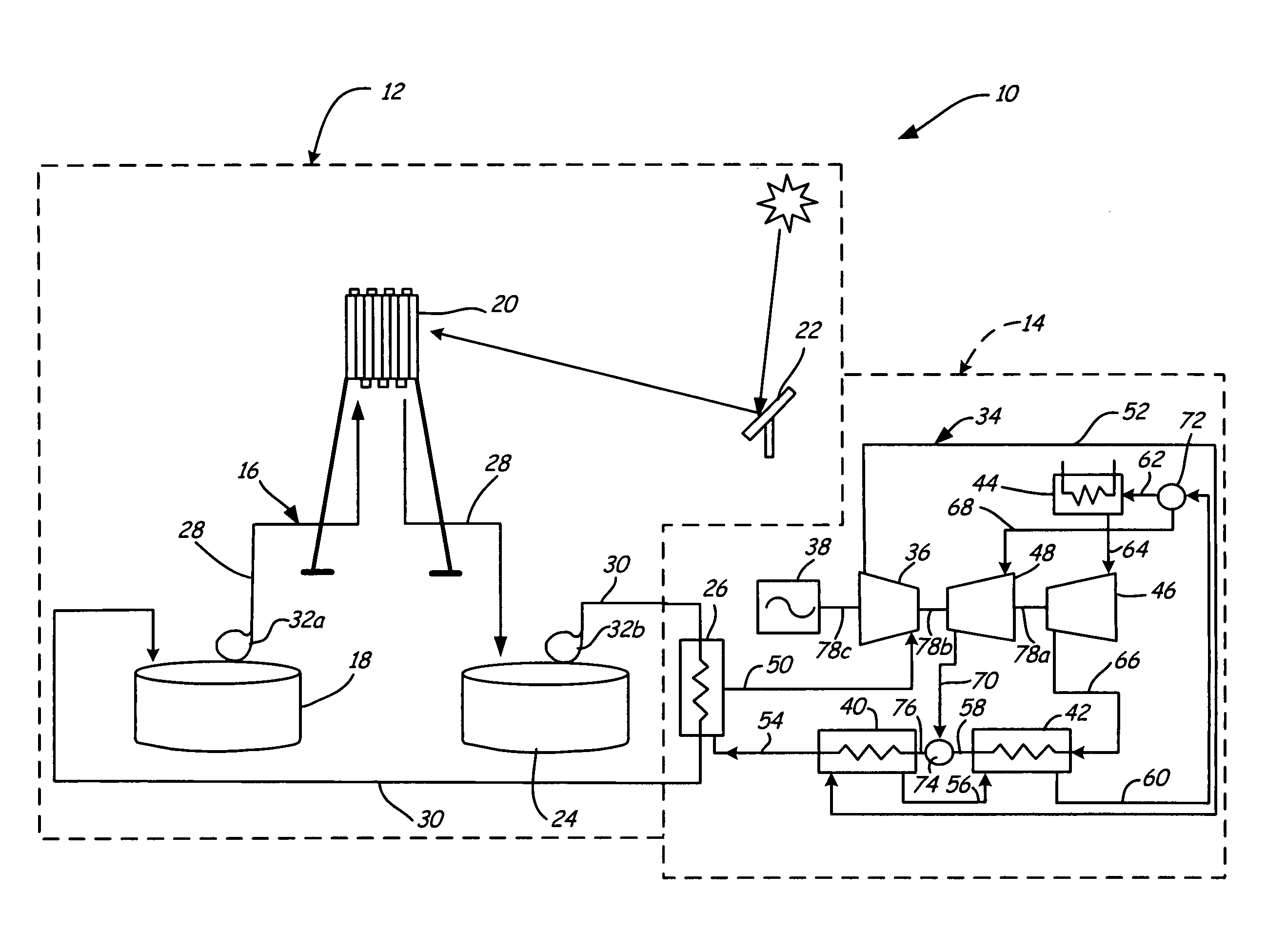
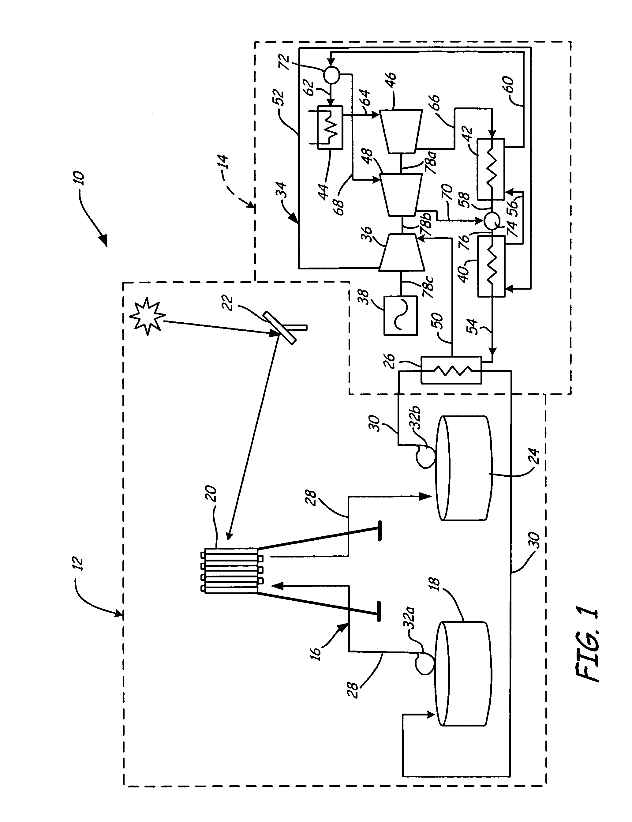
[0009]FIG. 1 shows a schematic of turbine system 10, which generally includes solar heating system 12 and supercritical carbon dioxide turbine system 14. Solar heating system 12 is used to provide thermal energy to supercritical carbon dioxide turbine system 14 up to 24 hours a day. The use of solar heating system 12 in conjunction with supercritical carbon dioxide turbine system 14 allows for efficient use of supercritical carbon dioxide turbine system 14 and increases the electric conversion efficiency of supercritical carbon dioxide turbine system 14 to approximately 46%. This increases the overall efficiency of turbine system 10, reducing plant capital costs and electricity production costs.

[0010]Solar heating system 12 generally includes circulation system 16, cold storage tank 18, solar receiver 20, heliostats 22, hot storage tank 24, and heat exchanger 26. Circulation system 16 transports a heat transfer fluid through solar heating system 12 and generally includes primary lin...


PUM


Abstract

A solar-powered supercritical carbon dioxide turbine system includes a supercritical carbon dioxide turbine system and a solar heating system. The solar heating system has a molten salt heat transfer fluid for providing thermal energy to the supercritical carbon dioxide turbine system.

Description

BACKGROUND OF THE INVENTION[0001]The present invention relates generally to carbon dioxide turbines. In particular, the invention relates to carbon dioxide turbines powered by a renewable energy source.[0002]There is a continuing demand for clean renewable energy sources due to the depletion of the Earth's supply of fossil fuels and concerns over the contribution to global warming from combustion of fossil fuels. Solar power towers generate electric power from sunlight by focusing concentrated solar radiation on a tower-mounted receiver. Solar power tower systems typically include a “cold” storage tank, a solar receiver, heliostats, a “hot” storage tank, and an energy conversion system, such as a steam generator and turbine / generator set. In operation, a heat transfer fluid is pumped from the cold storage tank to the solar receiver. The heat transfer fluid can be any appropriate medium that has the capability to transfer heat and thermally maintain the heat in the medium, such as wa...

Claims


Application Information

Patent Timeline
Patent Type & Authority Patents(United States)
IPC IPC(8): F03G6/00
CPCF02C1/05F03G6/067Y02E10/46Y02P80/10Y02P80/20
Inventor LITWIN, ROBERT Z.ZILLMER, ANDREW J.HOFFMAN, NATHAN J.VON ARX, ALAN V.WAIT, DAVID
Owner SOLARRESERVE TECH
Why Eureka
Try Eureka