Measuring head for nanoindentation instrument and measuring method using same

a nano-indentation and measuring head technology, applied in the field of nano-indentation measuring instruments, can solve the problems of inability to apply completely, overestimating the penetration depth, and further worsening, and achieve the effect of accurate and reliable measurement of elastic modulus and hardness at a nano-scal

Active Publication Date: 2010-03-30
ANTON PAAR TRITEC SA
View PDF7 Cites 31 Cited by
  • Summary
  • Abstract
  • Description
  • Claims
  • Application Information

AI Technical Summary

Benefits of technology

[0013]The invention is based on the idea of using a measuring axis and a reference axis each having their own actuating means and their own means for measuring the displacement, and of measuring the applied force. The indentation measurement may therefore be conducted relatively to a reference, for which the force applied on the sample is controlled. Thus it is possible to achieve what is called active referencing of the surface of the sample to be measured, i.e., by independently controlling the reference axis, it is possible to get rid of any parasitic movement of the surface of the sample and / or of the measuring instrument itself, for example as a result of a change in temperature, of a deformation of the frame or of the frame-sample connection.

Problems solved by technology

Generally, with the cited devices of the prior art, several problems arise, such as the following:
The problem is further worsened if the instrument uses an electrodynamic actuator which itself produces heat and this depends on the generated force.
This deformation leads to overestimating the penetration depth and requires subsequent correction by subtraction of the estimated value of the compliance.
3) Independence of the force and displacement sensors. As indicated earlier, the existing nano-indentation heads are equipped with a single actuator and a single sensor (displacement sensor). The absence of an independent force sensor poses two problems.
First, the force is not directly measured but is estimated, which may be a source of error, and second, several very interesting loading modes—such as an indentation with a constant deformation rate for example—cannot be applied completely because they require a control which takes into account the penetration depth and the applied force simultaneously.

Method used


Image

  • Measuring head for nanoindentation instrument and measuring method using same
  • Measuring head for nanoindentation instrument and measuring method using same
  • Measuring head for nanoindentation instrument and measuring method using same

Examples


Embodiment Construction

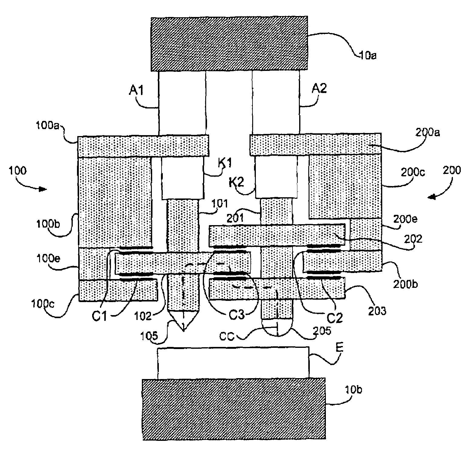
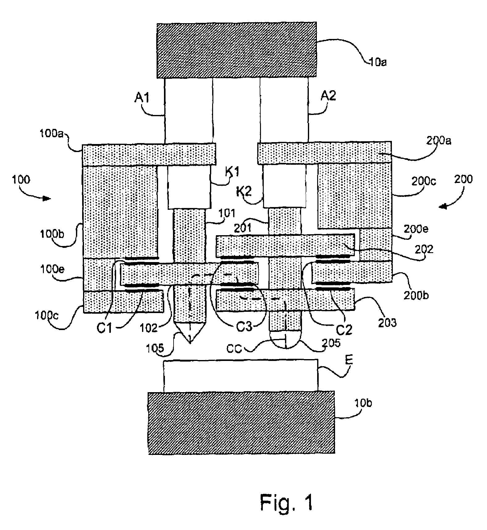
[0020]An exemplary embodiment of a measuring head by nano-indentation according to the principles of the invention is schematically illustrated in FIG. 1. This measuring head has, attached to the frame 10 of the measuring instrument, two symmetrical and independent axes, one of the axes corresponding to the actual indentor and the second axis corresponding to the reference. Thus, for the axis corresponding to the indentor and called a measuring axis, an actuator A1, preferably of the piezoelectric type, attached to the frame 10a, a spring K1 and a rod 101 ending with the indentor 105, are found. The rod 101 includes a transverse component 102 which bears lower and upper electrodes, which cooperate with matching electrodes on the portions 100b and 100c of the body 100 so as to form a force sensor in the form of two capacitors C1, mounted differentially so as to measure the deformation of the spring K1. The body 100, which includes the portions 100a-100e, is attached by its portion 10...


PUM

PropertyMeasurementUnit
penetration depthsaaaaaaaaaa
DC voltageaaaaaaaaaa

Abstract

A measuring head for a nano-indentation instrument capable of positioning a sample relatively to the measuring head, which includes a measuring axis, a reference axis and a component for detecting a depth of penetration of an indentor into the sample. The measuring and reference axes are attached to a frame for connection to the instrument. The measuring axis incorporates an actuator and includes the indentor, the reference axis incorporates an actuator and includes a reference tip, and the measuring and reference axes each have a component for detecting a force applied by its actuator. Penetration depth is detected by measuring a displacement of the indentor relatively to the reference tip.

Description

BACKGROUND OF THE INVENTION[0001]1) Field of Invention[0002]The present invention generally relates to nano-indentation measuring instruments and more particularly to a measuring head for such an instrument as well as to its method of use, said head using active referencing of the surface of the sample to be measured.[0003]2) Description of Related Art[0004]The measuring method by instrumented indentation (Depth-Sensing Indentation or DSI) is one of the most used methods for determining certain mechanical properties of materials, such as for example the elastic modulus and hardness. This method consists of applying an increasing and subsequently a decreasing force on a sample via a tip or indentor, with a determined shape in order to investigate and to measure, continuously and simultaneously, the values of the load, of the load alleviation, respectively, applied onto the sample on the one hand, and the penetration depth of the indentor on the other hand. The involved forces may be ...

Claims


Application Information

Patent Timeline
Patent Type & Authority Patents(United States)
IPC IPC(8): G01N3/48
CPCG01N3/42G01Q60/366B82Y35/00G01N2203/0051G01N2203/0286
Inventor WOIRGARD, JACQUESBELLATON, BERTANDCONSIGLIO, RICHARD
Owner ANTON PAAR TRITEC SA
Why Eureka
Try Eureka