Method for manufacturing a dental restoration

a technology for dental restorations and manufacturing methods, which is applied in the direction of dental prosthetics, additive manufacturing, dental preparations, etc., can solve the problems of increasing the shrinkage of bound ceramic powder, unable to predict shrinkage in all directions, and not being able to use this technology in dental restoration applications

Inactive Publication Date: 2010-03-30
DEGUDENT
View PDF13 Cites 26 Cited by
  • Summary
  • Abstract
  • Description
  • Claims
  • Application Information

AI Technical Summary

Benefits of technology

[0022]In yet another preferred embodiment the non-cohesive form of the material to be applied can be one of powder form, liquid, thin slices and so on. This is related to the method to be applied for providing cohesion therein. In a powder form the cohesion can for instance be given by selectively adding binder to the powder or by subjecting the powder to the action of at least one laser. Particularly in the case of liquid forms of the material to be applied, an arrangement with two lasers can be used depending on the capacity of this liquid material to transmit laser light, where the intended effect of providing cohesion, for instance solidifying, only occurs where the laser beams coming from the lasers cross each other. In an embodiment with thin slices colour variations can be realized per slice around the periphery thereof, or the slices can be manufactured from homogenous material.

Problems solved by technology

Owing to the development of new materials and machines, the possibilities in the field of 3D printing have recently been greatly expanded, although there is still no application known for using this technology for dental restorations.
A drawback to the use of starch as binder is that it increases the shrinkage of the bound ceramic powder and that the shrinkage can moreover not be predicted in all directions.
This makes starch less useful for the accuracy desired in dentistry.

Method used


Image

  • Method for manufacturing a dental restoration
  • Method for manufacturing a dental restoration

Examples


Embodiment Construction

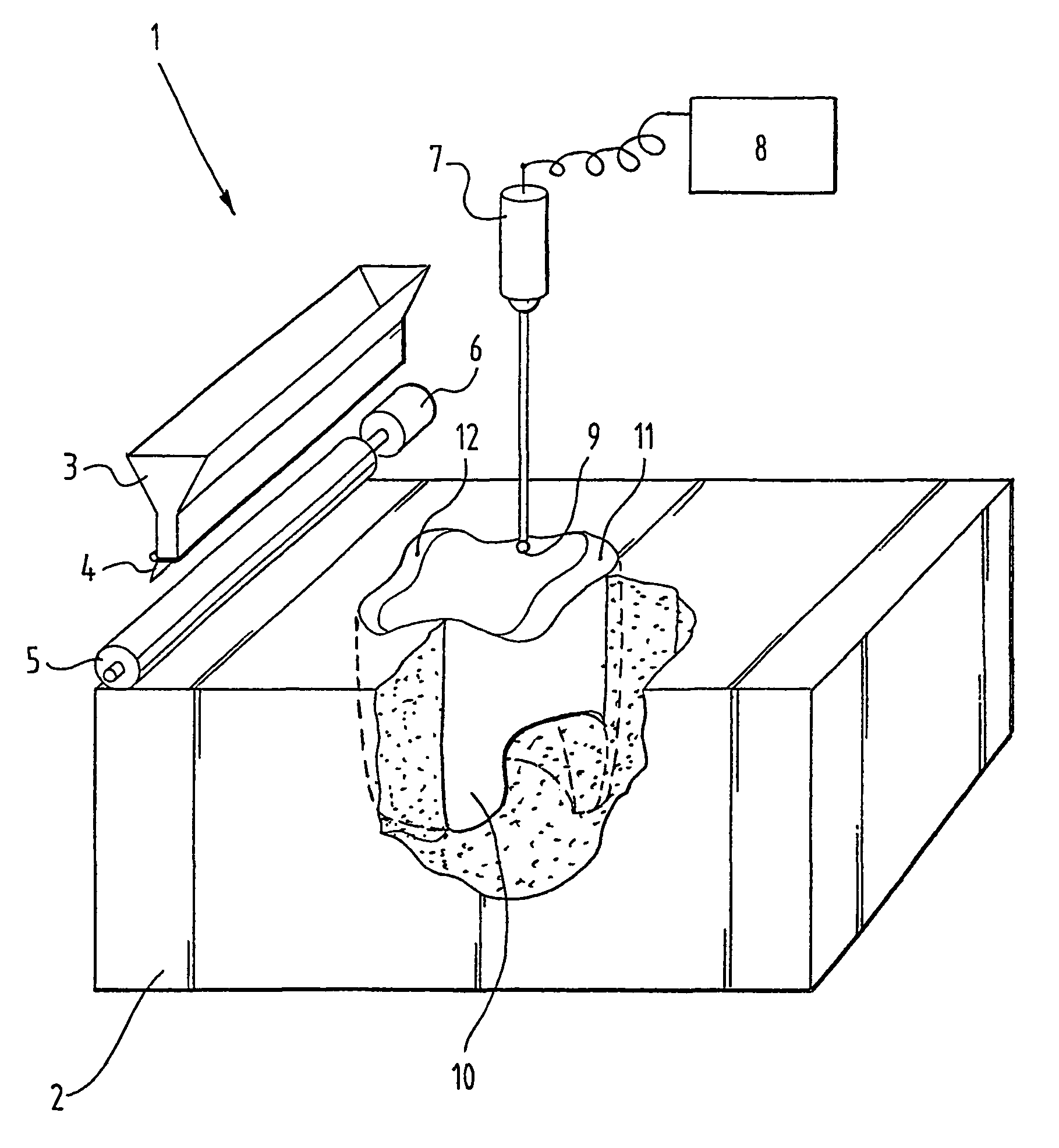
[0027]Installation 1 comprises a holder (not shown) in which layers of powder-form yttrium-stabilized tetragonal zirconium oxide (Y-TZP) can be placed one over another. The zirconium oxide is in powder form so that a body 2 of this powder is formed as the stacking of said layers onto each other progresses.

[0028]The layers are arranged using a powder holder 3, which in this embodiment is funnel-shaped and adapted to pour a measured quantity. Powder holder 3 is provided for this purpose with a flap 4 with which the pouring opening of powder holder 3 can be closed.

[0029]If a quantity of powder-form zirconium oxide from powder holder 3 is poured, either at one location or spread over the upper surface of the body 2 formed so far, the upper surface is leveled using a driven roller 5 which is coupled to a motor 6. The powder-form zirconium oxide is not only leveled, but also compressed and compacted to the desired extent.

[0030]The installation further comprises a laser generator 7 connect...


PUM

PropertyMeasurementUnit
bending strengthaaaaaaaaaa

Abstract

A method for manufacturing a dental restoration, including: determining an external form and dimensions available for a completed restoration; obtaining an image of a natural tooth to be replaced with the restoration or a tooth corresponding therewith, wherein the image comprises at least the external surface visible in use of the to be replaced or corresponding tooth, with variations in the appearance therein; defining locally on and at least to visible depth below the surface of appearance-determining properties of at least one material to be applied for the restoration in accordance with the obtained image and the variations in the appearance therein; constructing the restoration, including the steps of: providing at least one material to be applied in non-cohesive form; and providing cohesion to the material in accordance with the available form and dimensions.

Description

BACKGROUND OF THE INVENTION[0001]1. Field of the Invention[0002]The present invention relates to a method for manufacturing a dental restoration.[0003]2. Description of the Related Art[0004]Different methods are known in the art for manufacturing a dental restoration, wherein these methods are mainly determined by the type of materials used.[0005]Ceramic materials have been successfully applied for many years in dental restorations. The two most important functions of restorative ceramics are aesthetics and strength. However, most dental ceramics do not fulfil both functions. Different porcelains and glass ceramics are used for aesthetic applications. These have a natural tooth colour and translucence but have a relatively low three-point bending strength (50-200 MPa).[0006]Higher-strength materials have been developed as basic core material. These materials have a three-point bending strength of 150 to 500 MPa, but are generally too opaque and must be combined with translucent porc...

Claims


Application Information

Patent Timeline
Patent Type & Authority Patents(United States)
IPC IPC(8): A61C13/00B29C35/08A61C9/00A61C13/08A61K6/02A61K6/027
CPCA61C13/0004A61C13/082A61C9/004A61C13/0019A61C9/0053B33Y80/00
Inventor VAN DER ZEL, JOSEPH M.
Owner DEGUDENT
Why Eureka
Try Eureka