Two-component developer and two-component developing apparatus using the same

a technology of two components and developing apparatus, applied in the field of two-component developer and two-component developing apparatus, can solve the problems of image fogging and toner scattering, too small charge amount of toner, and low electrical resistance of toner, so as to excellent adhesiveness, and suppress image density insufficiency

Inactive Publication Date: 2010-03-30
SHARP KK
View PDF34 Cites 11 Cited by
  • Summary
  • Abstract
  • Description
  • Claims
  • Application Information

AI Technical Summary

Benefits of technology

[0038]According to the invention, it is preferable that the coating layer of the carrier further comprises silicone resin together with the acrylic resin. When, together with the acrylic resin, the silicone resin is contained in the coating layer of the carrier, the toner is prevented from being melted and attached onto the carrier surface while the developer is agitated, so that the charging characteristics of the carrier are prevented from changing over repeated use. Therefore, the charge amount of the toner can be kept constant over a long period and uniform images can be provided.
[0044]According to the invention, a two-component developing apparatus includes developer supplying means including a developer holding member, and control means, and the two-component developer of the invention is supported by the developer holding member and is conveyed to the position in which the latent image formed on the latent image bearing member is to be developed (hereinafter, referred to as “development position”). At this time, the control means controls the operation of the developer supplying means such that the moving direction of the developer holding member at the development position is opposite (this direction is referred to as “counter direction”) to the moving direction of the latent image bearing member at the development position. With this, the two-component developer of the invention is supplied to a latent image formed on the latent image bearing member by the developer holding member that moves in the opposite direction to the latent image bearing member, and the latent image formed on the latent image bearing member is developed by the two-component developer of the invention. In the two-component developing apparatus in which the developer holding member moves in the counter direction with respect to the latent image bearing member, a mechanical load applied to the two-component developer is large at the opposing portion of the developer holding member and the latent image bearing member, so that the coating layer of the carrier contained in the two-component developer is detached, and the hot offset phenomenon may occur in the fixing apparatus of the image forming apparatus. However, in the two-component developing apparatus of the invention, the carrier contained in the two-component developer of the invention used as a two-component developer has excellent adhesiveness between the carrier core material and the coating layer, and the coating layer is hardly detached, and even if the coating layer is detached and mixed with the toner, the acrylic resin contained in the coating layer functions as a parting agent, and therefore, in the two-component developing apparatus, the hot offset phenomenon hardly occurs at the time of fixing. Therefore, by using the two-component developing apparatus of the invention as an image forming apparatus, a reduction in the hot offset occurrence temperature due to detachment of the coating layer of the carrier can be prevented, so that the temperature at which the toner is heated by the fixing member during fixing can be set to a temperature at which the toner can be fixed on a recording material at a sufficient strength, and thus mages having excellent fixing strength can be realized.

Problems solved by technology

Furthermore, the image forming apparatus is required to form uniform images over a long time, so that for the two-component developer, it is required that the charging characteristics of the toner and the charging ability of the carrier to the toner are stabilized over a long time.
However, since carbon black has conductivity, when the concentration of carbon black in the toner is 10% by weight or more, as in the technique disclosed in JP-A 7-77828, the electrical resistance of the toner becomes too low, and the charge amount of the toner becomes too small, so that problems such as image fogging and toner scattering are caused.
When the carrier lifting occurs, the carrier is transferred to a recording material together with the toner, so that critical image defects such as partial transfer defects are caused.
However, when the surface of magnetic particles, which serve as a carrier core material, is coated only with resin, the electrical resistance of the carrier becomes too high, so that the problem that images are degraded because of the edge effect and the phenomenon of accumulation of charges is caused.
Therefore, the fixing strength for images is decreased, which is a problem.
However, in the technique disclosed in Japanese Patent No. 2683624, the charging characteristics of the toner are not taken into consideration.
Therefore, depending on the charging characteristics of the toner, an appropriate charge amount of the toner cannot be obtained, and image density insufficiency, image fogging and toner scattering may result.
In particular, when the size of the particles of the toner is reduced, for example, such a size that the volume average particle diameter is about 6 to 9 μm, in order to meet recent requirements of higher definition and higher quality for images, the specific surface area of the toner increases, and the charging ability of the carrier to the toner becomes insufficient.
As a result, the charge amount of the toner is reduced, and image fogging and toner scattering tend to occur.

Method used


Image

  • Two-component developer and two-component developing apparatus using the same
  • Two-component developer and two-component developing apparatus using the same
  • Two-component developer and two-component developing apparatus using the same

Examples


example 1

[0165][Production of Toner]

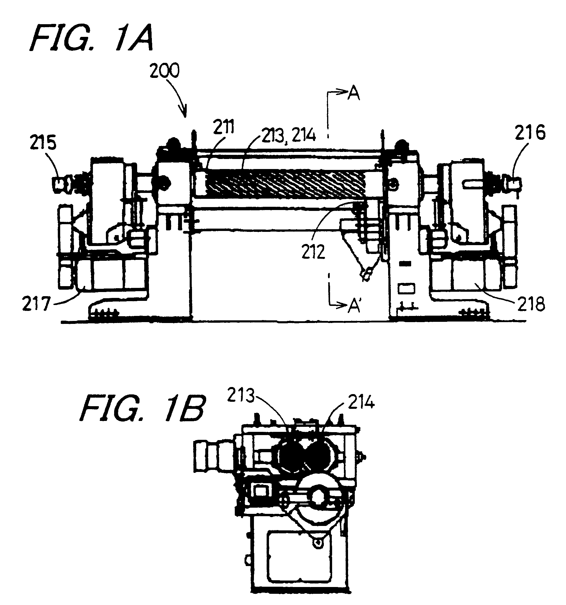
[0166]10 kg of raw material that was weighed at a proportion of 40 parts by weight of carbon black (product name: #44, particle diameter: 24 nm manufactured by Mitsubishi Chemical Co., Ltd) with respect to 60 parts by weight of polyester resin (product name: EP208, manufactured by Sanyo Chemical Industries Ltd.) was mixed for 3 minutes at 700 rotation of the agitating blade per minute (700 rpm) with HENSCHEL MIXER. The obtained raw material mixture was supplied in a predetermined amount to a continuous two-roller type kneader as shown in FIGS. 1A and 1B with a table feeder and was melted and kneaded and thus a kneaded product was obtained. This kneaded product was cooled, and then roughly ground in a hummer type grinder, using a screen having a pore diameter of 2 mm, and thus a kneaded and roughly ground product was obtained.

[0167]The running conditions of the continuous two-roll type are as follows:

[0168]Roll diameter: 0.12 m

[0169]Effective roll length: 0...

example 2

[0184]The two-component developer of Example 2 was produced in the same manner as Example 1, except that when producing the carrier, the mixing amount of the silicone resin was changed to 65 parts by weight, and that the mixing amount of the acrylic resin was changed to 30 parts by weight.

example 3

[0185]The two-component developer of Example 3 was produced in the same manner as Example 1, except that when producing the carrier, the mixing amount of the silicone resin was changed to 45 parts by weight, and that the mixing amount of the acrylic resin was changed to 50 parts by weight.


PUM


Abstract

A two-component developer is provided in which the reduction of the hot offset occurrence temperature due to detachment of the coating layer, image density insufficiency, image fogging and toner scattering and the like can be suppressed. In the two-component developer including a toner and a carrier, the content of acrylic resin in a coating layer of the carrier is in a range from 5 to 50% by weight based on the total amount of the coating layer, and the dielectric loss (tan δ) is in the range from 4.0×10⁻³ to 15.0×10⁻³. By using the two-component developer, the reduction of the hot offset occurrence temperature in a fixing apparatus can be prevented. Further, image density insufficiency, image fogging and toner scattering and the like can be suppressed, with a result that images having high quality and sufficient image density can be obtained.

Description

[0001]This application is a new U.S. patent application and claims priority to JP 2004-181663, filed 18 Jun. 2004, the entire content of which is hereby incorporated by reference.BACKGROUND OF THE INVENTION[0002]1. Field of the Invention[0003]The invention relates to a two-component developer and two-component developing apparatus used for visualizing latent images such as electrostatic latent images in a method for forming images such as electrophotography and electrostatic recording.[0004]2. Description of the Related Art[0005]In electrophotography widely used in image forming apparatuses such as copiers and printers, images are formed in the following manner, utilizing the photoconduction phenomenon with photoconductive materials (e.g., see U.S. Pat. No. 2,297,691, Japanese Examined Patent Publication JP-B2 42-23910 (1967), and Japanese Examined Patent Publication JP-B2 43-24748 (1968)). First, a photosensitive member provided with photosensitive layer containing photoconductive ...

Claims


Application Information

Patent Timeline
Patent Type & Authority Patents(United States)
IPC IPC(8): G03G9/113G03G9/08G03G9/09G03G9/107
CPCG03G9/0821G03G9/09G03G9/107G03G9/1133G03G9/1135G03G9/1138G03G9/1139G03G9/1085
Inventor KATAOKA, TOSHIHARUSAKAI, MASAHIRO
Owner SHARP KK
Why Eureka
Try Eureka