Pressure isolation plug for horizontal wellbore and associated methods

a technology of pressure isolation and plugs, which is applied in the direction of drilling casings, drilling pipes, and well accessories, can solve the problems of difficult operation of moving completion equipment, such as plugs, perforating guns, setting tools, etc., and the use of tractors or coil tubing in horizontal applications can be very time-consuming and expensive, so as to facilitate the deployment of plugs and facilitate the pumping

Inactive Publication Date: 2010-04-06
WEATHERFORD TECH HLDG LLC
View PDF55 Cites 107 Cited by
  • Summary
  • Abstract
  • Description
  • Claims
  • Application Information

AI Technical Summary

Benefits of technology

[0009]A wellbore pressure isolation plug is deployed in a wellbore and has a sealing element that can be activated to seal against an interior surface of a surrounding tubular. Once set, a ball valve in the plug restricts upward fluid communication through the plug, and another ball valve in the plug can restrict downward fluid communication through the plug. To facilitate deployment of the plug in a horizontal section of the wellbore, the plug has a plurality of rollers positioned on a distal body portion. In addition, the plug has a ring disposed about its body between the distal body portion and an adjacent body portion. This ring has an outside diameter at least greater than that of the adjacent body portion. The increase diameter ring enhances a pressure differential across the plug that facilitates pumping of the plug in the wellbore, and especially within a horizontal section of the wellbore.

Problems solved by technology

Unfortunately, moving completion equipment, such as perforating guns, setting tool, and plugs, in a horizontal section of a wellbore can prove difficult for operators.
As one skilled in the art will appreciate, the use of tractors or coil tubing in horizontal applications can be very time consuming and expensive.

Method used


Image

  • Pressure isolation plug for horizontal wellbore and associated methods
  • Pressure isolation plug for horizontal wellbore and associated methods
  • Pressure isolation plug for horizontal wellbore and associated methods

Examples


Embodiment Construction

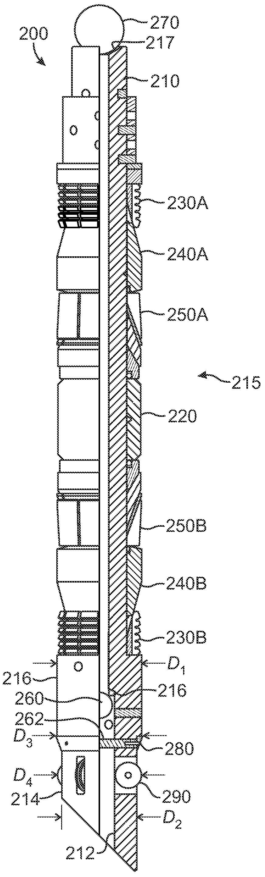
[0020]Referring to FIG. 2A, a plug 200 according to one embodiment of the present disclosure is illustrated in partial cross-section. The plug 200 includes a mandrel 210 and a sealing system 215 disposed about the mandrel 210. The sealing system 215 includes a packing element 220, slips 230A-B, cones 240A-B, and retainers 250A-B, similar to the components disclosed in U.S. Pat. No. 6,712,153, which is incorporated herein by reference in its entirety. The plug 200 and sealing system 215 can also be composed of non-metallic components made of composites, plastics, and elastomers according to the techniques disclosed in incorporated U.S. Pat. No. 6,712,153.

[0021]When used in a wellbore, the plug 200 is essentially actuated in the same way discussed previously to form a pressure isolation seal between the packing element 220 and the inner wall of surrounding casing or the like. For example, the plug 200 can be deployed in the wellbore using any suitable conveyance means, such as wirelin...


PUM


Abstract

A wellbore pressure isolation apparatus is deployed in a wellbore and has a sealing element that can be activated to seal against an interior surface of a surrounding tubular. Once set, a ball valve in the apparatus restricts upward fluid communication through the apparatus, and another ball valve in the apparatus can restrict downward fluid communication through the apparatus. These ball valve can have disintegratable balls intended to disintegrate in wellbore conditions after different periods of time. To facilitate deployment of the apparatus in a horizontal section of the well bore, the apparatus has a plurality of rollers positioned on a distal end. In addition, the apparatus has a ring disposed about the body between the distal body portion and an adjacent body portion. The ring has an outside diameter at least greater than that of the adjacent body portion to facilitate pumping of the apparatus in the wellbore.

Description

FIELD OF THE DISCLOSURE[0001]The subject matter of the present disclosure generally relates to pressure isolation plugs for oil and gas wells and more particularly to pressure isolation plugs that can be advantageously deployed in wellbores having horizontal sections.BACKGROUND OF THE DISCLOSURE[0002]FIG. 1A shows a cross-sectional view of a wellbore 10 having a casing 20 positioned through a formation. Typically, the casing 20 is set with concrete to strengthen the walls of the wellbore 10. Once the casing 20 is set, various completion operations are performed so that oil and gas can be produced from the surrounding formation and retrieved at the surface of the well. In the completion operations, completion equipment, such as perforating guns, setting tool, and pressure isolation plugs, are deployed in the wellbore 10 using a wireline or slick line.[0003]The wellbore 10 is shown in a stage of completion after perforating guns have formed perforations 13, 15 near production zones 12...

Claims


Application Information

Patent Timeline
Patent Type & Authority Patents(United States)
IPC IPC(8): E21B33/12
CPCE21B33/134E21B23/00E21B23/08E21B33/12E21B33/128
Inventor TURLEY, ROCKYMCKEANCHNIE, JOHN
Owner WEATHERFORD TECH HLDG LLC
Why Eureka
Try Eureka