
Light guide member, illumination apparatus, and image capturing apparatus using the same

a technology of illumination apparatus and light guide member, which is applied in the direction of lighting and heating apparatus, instruments, and person identification, etc., can solve the problems of limiting the incorporation of image capturing apparatus, affecting the cost reduction, and affecting the effect of cost reduction

Active Publication Date: 2010-04-06
FUJITSU LTD +1
View PDF23 Cites 2 Cited by
  • Summary
  • Abstract
  • Description
  • Claims
  • Application Information

AI Technical Summary

Benefits of technology

[0022]It is still another object of the present invention to provide a light guide member and an illumination apparatus for uniformly illuminating an object even when using a point light source, and an image capturing apparatus for realizing cost reduction using the light guide member and the illumination apparatus.
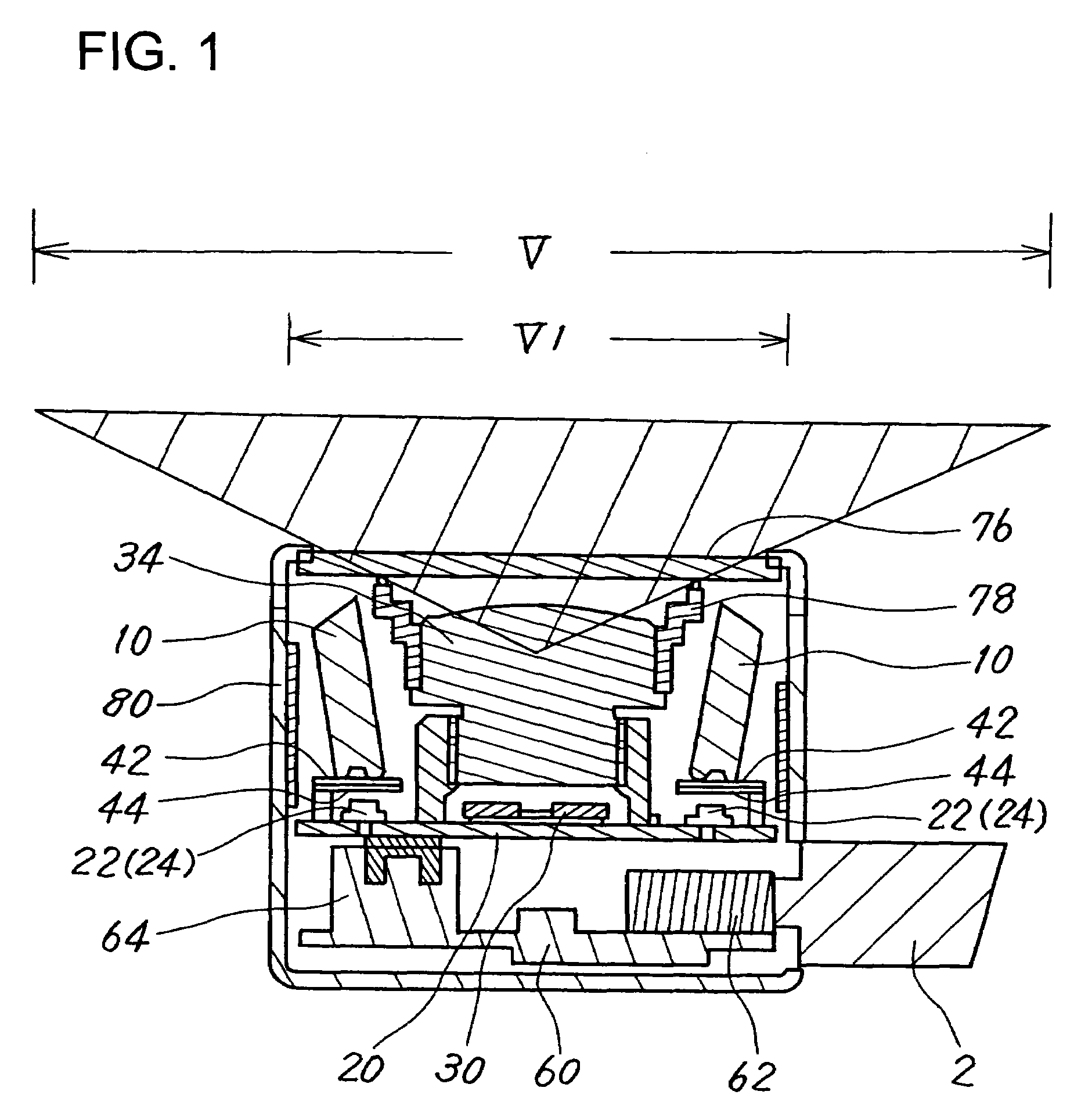
[0033]According to the present invention, a groove is provided on the lower end of the light guide member having a pair of side faces disposed oppositely, for receiving light output from the point light source and diffusing the light output from the point light source to at least three directions from the incident side toward the output side. Thus, by generating light components having directions resulting from reflection on the side faces, light to a multiplicity of directions can be output from the cylindrical-shaped light guide member, and thus, uniform illumination can be performed over a wide range. Because the ring-shaped light guide member can sufficiently be prepared simply by means of formation, cost reduction is effectively achieved, and miniaturization of the illumination mechanism and the imaging mechanism can also be attained.

Problems solved by technology

Therefore, it is difficult to miniaturize the image capturing apparatus.
Also, there is a restriction when incorporating the image capturing apparatus into equipment.
As a result, the necessity of two printed circuit boards at the minimum has impeded the cost reduction.
Also, the need of two printed circuit boards also causes difficulty in miniaturizing the image capturing apparatus.
Therefore, it is not suitable to obtain uniform light intensity over a plane having a certain area of an image capturing range.

Method used


Image

  • Light guide member, illumination apparatus, and image capturing apparatus using the same
  • Light guide member, illumination apparatus, and image capturing apparatus using the same
  • Light guide member, illumination apparatus, and image capturing apparatus using the same

Examples


Embodiment Construction

[0059]The preferred embodiment of the present invention is described hereinafter referring to the charts and drawings, in the order of an image capturing apparatus configuration, an illumination mechanism, an image processing configuration, and other embodiments. However, it is to be noted that the scope of the present invention is not limited to the embodiments described below.

Image Capturing Apparatus

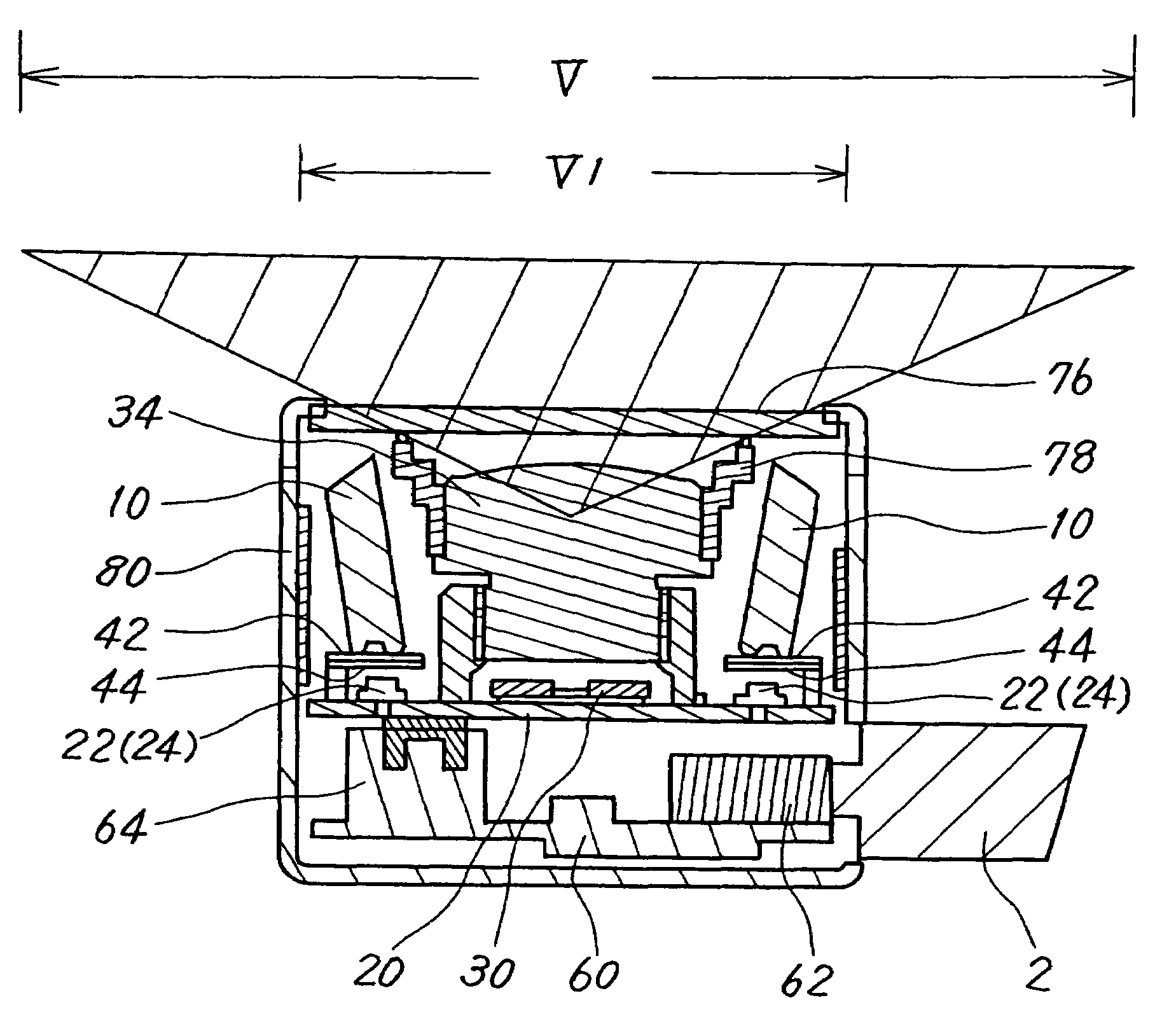
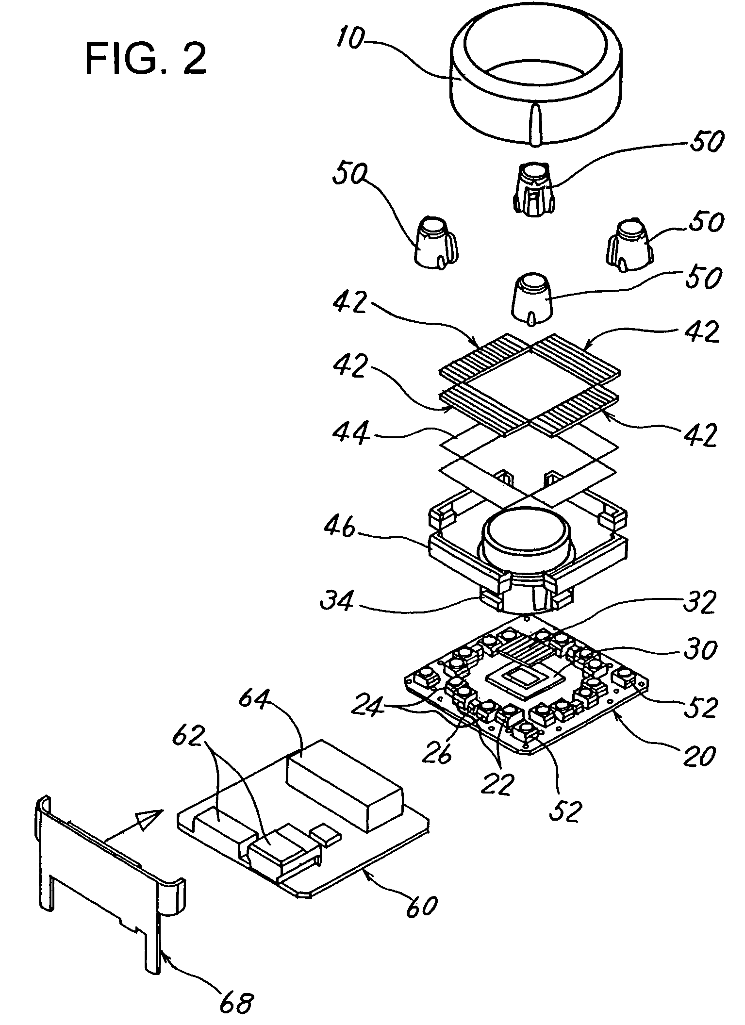
[0060]FIG. 1 shows a cross-sectional view of an image capturing apparatus according to one embodiment of the present invention; FIG. 2 shows an exploded structural view of the image capturing apparatus shown in FIG. 1; FIG. 3 shows a top plan view of the circuit board shown in FIGS. 1, 2; FIG. 4 shows an operation explanation diagram of a light-emitting device and a photodetector device shown in FIG. 3; FIG. 5 shows an assembly diagram when the structures shown in FIG. 2 are assembled; FIG. 6 shows a configuration diagram of the external case shown in FIG. 1; FIG. 7 shows a configurat...


PUM


Abstract

A light guide member illuminates with uniform light intensity distribution using the point light source light. On the lower end of the light guide member having a pair of side faces disposed oppositely, a groove is provided for receiving light output from each point light source and diffusing the above received light to at least three directions from the incident side toward the output side. Light components having directions using side-face reflection are generated in the light guide member, enabling light output to multiple directions from the cylindrical-shaped light guide member, and uniform illumination over a wide range. By using the ring-shaped light guide member, cost reduction is effectively achieved, and miniaturization of the illumination mechanism and the image capturing mechanism can also be attained.

Description

CROSS-REFERENCE TO RELATED APPLICATIONS[0001]This application is based upon and claims the benefit of priority from the prior Japanese Patent Application No. 2006-058087, filed on Mar. 3, 2006, the entire contents of which are incorporated herein by reference.BACKGROUND OF THE INVENTION[0002]1. Field of the Invention[0003]The present invention relates to a light guide member and an illumination apparatus for guiding light emitted from a plurality of light-emitting devices to an object, and irradiating the object, and an image capturing apparatus for capturing an image of the object using the same, and more particularly a light guide member and an illumination apparatus for uniformly irradiating a predetermined range of the object with light emitted from a plurality of light-emitting devices functioning as point light sources, and an image capturing apparatus using the same.[0004]2. Description of the Related Art[0005]An image capturing apparatus for capturing an image in a predeterm...

Claims


Application Information

Patent Timeline
Patent Type & Authority Patents(United States)
IPC IPC(8): G02B6/00G06V10/141G06V40/14
CPCG02B6/0001G06K9/2027G06K9/00375A61B5/117H01H2219/062G06K2009/00932G06V40/107G06V40/14G06V10/141G03B15/00H04N23/00G06F18/00
Inventor MATSUO, KOICHINISHIO, CHIKARA
Owner FUJITSU LTD
Learn More